Philips Philicorda · Volume 3
The ZA1001 Divider Stage
The tube, the stage circuit with its real values, and how a kick from the stage above makes a neon oscillator divide by two
Each of the Philicorda’s seventy-three neon stages is built from five parts: one small glass tube, one resistor, two capacitors and either a diode or, on the first stage, a coupling to the oscillator. Left to itself, such a stage is a relaxation oscillator — a capacitor charging through a resistor until the tube strikes and empties it, over and over, at a rate set by the resistor, the capacitors and the tube. What turns it into a divider is a small trimmer capacitor that carries a sharp negative kick from the stage above every time that stage fires. With the stage’s own period set a little longer than two of those kicks, the first kick arrives too early to fire it and the second one fires it; the stage settles into running at exactly half the rate of the stage above. This volume describes the tube, draws the stage with the values from the 22GM751 service manual, and explains the kick.
3.1 The ZA1001 tube
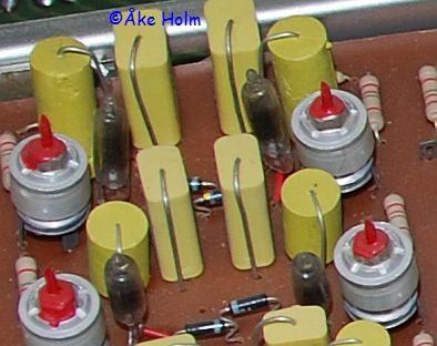
The ZA1001 is a member of a Philips family of small cold-cathode tubes made for switching and timing rather than for use as indicator lamps. Radiomuseum’s entry calls it a “neon switching diode with close tolerance of striking and extinction voltages”, usable “as oscillator or voltage level detection and indication”, and lists it under the Mullard, Miniwatt (1966) and Valvo (1968) brands of the Philips group (radiomuseum, ZA1001). It is a two-lead, all-glass tube of roughly 6 mm × 25 mm. It has no starter electrode, so it is a diode, not a trigger tube.
The family’s construction is described in detail by Ronald Dekker for its sibling, the ZA1002, and covered in Vol 3 of the Neon Ring Counters dive: a molybdenum rod cathode inside a cylindrical mesh anode, with the cathode deliberately sputtered during manufacture to give tight, stable striking voltages without the ageing of the older barium-coated neons (dos4ever.com). For the ZA1001 in particular, Dekker’s account and a widely copied tube-type list both say the gas fill includes a trace of a heavy gas, krypton or xenon, which slows de-ionisation and suits it to low-frequency relaxation oscillators — exactly the job the Philicorda gives it.
Three things about the ZA1001 could not be confirmed for this dive, and are worth stating because they circulate as facts:
- Its striking and maintaining voltages. No Philips, Mullard or Valvo data sheet for the ZA1001 was found. Figures of 120–135 V striking and 93 V maintaining appear in a forum thread about replacing Philicorda tubes, but those are exactly the published figures for the ZA1000 (lampes-et-tubes.info) and may have been carried across from it. They are not used as ZA1001 data here.
- Whether it is tritium-primed. The ZA1000 and ZA1002 are primed with tritium, which keeps the gas slightly ionised so the tube strikes promptly. Whether the ZA1001 contains tritium as well as its heavy gas is not confirmed. If it does, the priming has had five half-lives (12.3 years each) to decay since the 1960s — the problem the Neon Ring Counters dive describes for the ZA1002.
- Its marking. The ZA100x tubes carry a coloured dot rather than a printed type number. A seller of new old stock describes ZA1001s with a brown dot, “as described in the data sheet” (Circuits Online 116294); the ZA1002 is red, per its data sheet. Brown for the ZA1001 rests on that one statement.
The related tubes in the Philicorda, for comparison:
Table 1 — The related tubes in the Philicorda, for comparison
| Tube | What it is | Data | Role in the Philicorda |
|---|---|---|---|
| ZA1001 | two-electrode neon switching diode, heavy-gas additive | not found | 68–70 divider and sync stages |
| Z70U | three-electrode cold-cathode trigger tube | 350 V anode max, 12 mA max; typically 250 V at 3 mA (tubedatabase) | 3–5 of the lowest divider stages |
| ZZ1000 | voltage-reference tube | about 81–82 V at 3.2 mA (tubedatabase) | reference for the divider-rail regulator |
| ZA1000 | sibling switching diode, tritium-primed | 120–135 V strike, 93 V maintain, 1.5 mA | not used |
| ZA1002 | sibling switching diode, tritium-primed | 163–178 V strike, 109 V maintain (Philips data sheet) | not used |
The Z70U figures are from a tube database and were not checked against a Philips sheet.
3.2 The stage circuit
The schematic below shows the sync stage and the first dividing stage of the G note, simplified from Unit J of the 22GM751 service manual.
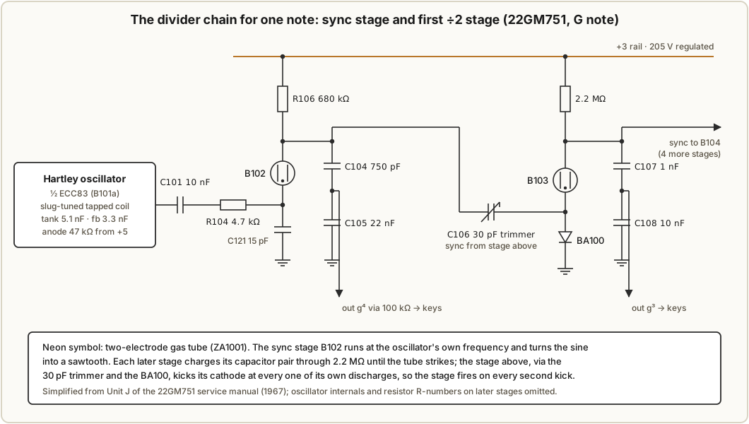
A dividing stage — B103 to B107 for the G note — has:
- an anode resistor of 2.2 MΩ from the +3 rail, which is regulated to 205 V (Vol 5);
- a pair of timing capacitors in series from the anode to ground — 1 nF and 10 nF on B103 — whose junction is the audio output;
- a BA100 diode from the tube’s cathode to ground, which carries the tube current when it strikes;
- a 30 pF trimmer capacitor from the anode of the stage above to this stage’s cathode.
The lowest stages of some chains add a 4.7 kΩ resistor in series at the anode, and the bottom stage of the E chain is a Z70U, discussed below.
The sync stage (B102) is different. Its anode resistor is a smaller 680 kΩ, its capacitors are 750 pF and 22 nF, and it has no diode: its cathode is driven directly by the oscillator through 10 nF and 4.7 kΩ, with 15 pF to ground. Each cycle of the sine wave pulls the cathode down far enough to fire the tube, so B102 runs at the oscillator’s own frequency. Its job is to turn the sine into a sawtooth, and to produce sharp edges that the next stage can lock to.
3.3 How the kick works
The manual does not explain the coupling in words; what follows is a reading of the schematic, consistent with the description by a Dutch repairer that the dividers are “triggerable neon oscillators” whose time constant is chosen “so that it always misses one pulse and divides by two” (Circuits Online 116294).
- Charging. Between firings the tube is dark, and the capacitor pair charges through 2.2 MΩ towards the 205 V rail. The cathode sits at about ground, held there by the diode.
- Firing. When the voltage across the tube reaches its striking voltage, the tube conducts and dumps the capacitors’ charge through itself and the BA100 to ground. The anode voltage drops quickly to near the tube’s maintaining voltage, the current falls too low to sustain the glow, and the tube goes out. The slow rise and fast drop are the sawtooth.
- The kick. That fast drop at this stage’s anode is coupled through the next stage’s 30 pF trimmer to the next stage’s cathode, pulling it sharply negative. The diode is now reverse-biased, so the cathode is free to move. For a moment the next tube sees its own anode voltage plus the kick across it.
- Fire or not. If the next stage’s capacitor has already charged to within a kick of its striking voltage, the kick fires it early. If not, the kick passes and changes nothing. The slow recovery of the upper stage’s anode produces only a small positive current through 30 pF, which the forward-biased diode clamps.
The RC of each stage is chosen so that, left alone, it would take a little longer than two input periods to reach its striking voltage. So the first kick after a firing always arrives too early, and the second always arrives just before the stage would have fired by itself — and fires it. The diagram below draws the sequence.
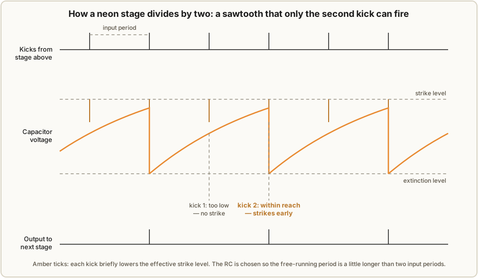
This is the same synchronisation that held the free-running timebase of a valve television to the broadcast sync pulses: an oscillator set to run slightly slow, pulled into step by being fired a little early, once per cycle, by an outside pulse. The trimmer sets how big the kick is, and so how far from its natural period a stage can be and still lock. Vol 4 follows that through to pitch.
3.4 The capacitor pair
The two timing capacitors do two jobs. In series they are the stage’s timing capacitance. Their junction is also a capacitive divider that takes a fraction of the anode’s sawtooth as the audio output: the larger lower capacitor sees only a small share of the swing. For B103 the share is 1 nF ÷ (1 nF + 10 nF), about 9 %; across the G chain it ranges from about 3 % to 9 %, presumably to balance the levels of the octaves at the key contacts, though the manual does not say.
The series capacitance can be checked against the frequency each stage runs at. For a neon relaxation
oscillator charging through R into C from a supply V, the period is T ≈ R·C·ln((V − Vm)/(V − Vs)),
where Vs is the striking voltage and Vm the voltage the capacitor falls to when the tube goes out (the
derivation is in Vol 2 of the Neon Ring Counters
dive). With R = 2.2 MΩ and the G chain’s values:
Table 2 — dive). With R = 2.2 MΩ and the G chain's values
| Stage | Series C | R·C | Output period | Period ÷ R·C |
|---|---|---|---|---|
| B103 (g³, 1568 Hz) | 0.909 nF | 2.00 ms | 0.638 ms | 0.32 |
| B104 (g², 784 Hz) | 1.89 nF | 4.15 ms | 1.276 ms | 0.31 |
| B105 (g¹, 392 Hz) | 4.12 nF | 9.07 ms | 2.551 ms | 0.28 |
| B106 (g, 196 Hz) | 8.57 nF | 18.9 ms | 5.102 ms | 0.27 |
| B107 (G, 98 Hz) | 17.2 nF | 37.9 ms | 10.20 ms | 0.27 |
The ratio stays close to 0.3 down the whole chain, which is what halving the frequency while doubling the
capacitance should give. It also says something about the tube. A ratio of 0.27–0.32 means
(V − Vm)/(V − Vs) is about 1.3–1.4; with V = 205 V and a striking voltage somewhere in the 120–135 V
range of its siblings, that puts the gap between striking and extinction at roughly 20–30 V. That is a
back-calculation that ignores the kick (which fires each stage slightly early) and the diode’s forward
drop, not a measurement — but it is the right order for a switching tube, and wider than the 12–20 V of a
common indicator neon.
3.5 The Z70U stages
On the Unit J schematic, the last stage of the E chain (B182, at about 82 Hz) is drawn as a three-electrode tube, a Z70U, with its third electrode fed from the +5 rail through 18 MΩ. That small, constant current keeps a little ionisation present in the tube, so that it strikes more predictably. The other four Z70Us of the GM751 are probably on the lowest stages of other notes, but only Unit J was examined for this dive. The manual does not say why those stages need a trigger tube, and the AG7500 uses three Z70Us rather than five.
3.6 Not a ring, and not a counter
The sibling Neon Ring Counters dive is about rings: several neon stages sharing a common anode, with a
single glow stepping from one to the next as input pulses arrive, so that a ring of N stages counts to
N. The Philicorda has no rings. Each note is a straight chain of separate oscillators, one tube per
octave, each locked to the one above.
That difference matters. A counter divides by counting input events, so its ratio is fixed by its structure; it can miscount, but it has no tendency to run at a different ratio. A synchronised oscillator divides because its own period happens to fit two input periods. Its ratio is exact while it is locked, but it depends on the stage’s timing staying inside a lock range — and if the timing drifts far enough, the stage will lock at a different ratio or not at all. Vol 4 is about exactly that.
Comments (0)