Neon Ring Counters · Volume 3
Which Tubes to Use
Indicator neons, purpose-built switching tubes, trigger tubes — and how to bin a boxful into ranks you can actually design around
Every neon ring counter is, at bottom, a bet that a handful of little glow lamps will
strike and extinguish at voltages close enough to one another that a single set of
resistor values can herd all of them. That bet is easy to win with the right tubes and
nearly impossible to win with the wrong ones, and the difference is not exotic — it is the
plain gap between the striking voltage Vs at which a tube lights and the maintaining
voltage Vm at which it goes dark, and how tightly that gap is held from one tube to the
next. Vol 2 established why a cold-cathode device has two different voltages and why the
hysteresis between them is what gives a glow lamp memory; this volume is about which
devices give you a usable amount of that hysteresis, where to find them in 2026, and — the
part no amount of clever circuit design can substitute for — how to sit at a bench and
measure a box of surplus lamps into ranked bins before you solder a single one. Get the
tubes and the binning right and the ring in Vol 4 almost designs itself; get them wrong and
no resistor value on Earth will make the glow march reliably.
3.1 The family tree of cold-cathode counting devices
There are, practically speaking, four kinds of gas-discharge device you might count with, and they form a clean hierarchy from “cheap and marginal” to “purpose-built and luxurious.”
- Ordinary indicator neons — the NE-2, NE-2H, NE-51 and the Soviet IN-3 (ИН-3).
These were made by the million to be pilot lamps, not switches. They work, but their
Vs−Vmwindow is small and their tube-to-tube spread is large. This is the class you will almost certainly build from, because it is the class you can actually buy, and it is the class that makes binning mandatory. - Purpose-built switching tubes — the Philips ZA1001 / ZA1002 family and their industrial cousins. These were engineered specifically to be bistable switches with a wide, repeatable hysteresis window and radioactive priming for fast, certain striking. They are wonderful and they are NOS-only.
- Trigger tubes — three-electrode cold-cathode tubes (the Z70U and its relatives) in which a small pulse on a third trigger (starter) electrode fires the main anode-to-cathode gap. They are the gas-filled cousin of a thyratron and behave as a latch or relay rather than as a self-transferring ring element; they matter to this series as a steering and buffering device more than as the ring’s counting stages.
- Dekatrons — a whole ten-stage ring integrated into one envelope, with a central anode, ten main cathodes and guide cathodes between them. These are important enough, and different enough, to get their own volume: Vol 5 covers them end to end. Mention them here only so the map is complete.
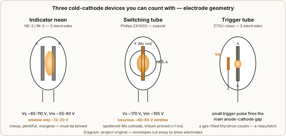
The figure below cuts the envelopes away on the three device types this volume is about, so you can see why their electrical behaviour differs — it is geometry and gas fill, nothing more mysterious than that.
3.2 Ordinary indicator neons — cheap, plentiful, and electrically marginal
The barium-coated cold cathode of a garden-variety NE-2 strikes somewhere around 65–110 V
(nominally about 90 V) and, once lit, will keep glowing until the voltage across it falls to
roughly 55–60 V. That leaves a Vs−Vm window of only about 12–20 V — and worse, the
window’s endpoints wander from tube to tube because the electrode spacing and the gas fill
were never held to switching-grade tolerances. Ronald Dekker put a number on exactly how
marginal this is: measuring a set of 21 ordinary neon tubes, he found an average striking
voltage of 68.8 V and an average maintaining voltage of 56.9 V, so the average
window was a meagre 12 V — and that is the mean, before you account for the spread that
makes one tube’s Vs overlap another tube’s Vm. Something like 99.99 % of every neon lamp
ever manufactured is this type, because “power-on indicator” never needed anything better.
Why does 12–20 V feel so tight? Because the ring counter has to fit two competing bias
requirements inside that same window at once (Vol 4 does the algebra in full). The cathode
transfer bias I·Rcat that steers the glow to the next stage has to be large enough to
overcome the tube-to-tube spread in Vs, yet small enough not to let a neighbouring
stage strike on its own. The ideal centre lands at about (Vs − Vm)/2 — so with a 15 V
window you are aiming a bias at roughly 7–8 V with a target the width of the spread itself.
On a marginal indicator neon the “keep it above the spread” floor and the “keep it below a
stray strike” ceiling are almost touching, and the only way to open daylight between them is
to shrink the spread — which is precisely what binning does. There is no cleverness that
substitutes for it; you either narrow the population or you fail.
The Soviet IN-3 deserves a specific note because it is the tube most modern builders actually use — it turns up on the surplus market in bulk, cheaply, and it is what Luc Small built his well-documented ring counter from (§3.6). It is electrically an indicator neon like any other: same order-of-magnitude window, same need for burn-in and binning, arguably even more spread because it is decades-old bulk NOS. Its virtues are availability and price, not consistency.
Two behavioural quirks of ordinary neons carry straight into ring-counter reliability, and
both were introduced in Vol 2. The first is photosensitivity (the “dark effect”): a
neon’s Vs drops under light — photo-electrons prime the gas — and rises, and becomes
erratic, in darkness. A ring built from bare indicator neons can therefore change its margins
between a lit room and a dark one, which is exactly the failure that later bit the PA3FWM
clock (it stopped counting in the dark until two priming LEDs were added — Vol 7). The second
is ageing: the Vs and Vm of a fresh neon drift most in the first hours of running as
the gas cleans up, then keep drifting slowly for life. Both quirks are the reason the
sequence for indicator neons is always burn in first, then measure, then bin — never
measure a cold tube and trust the number.
3.3 Purpose-built switching tubes — the Philips ZA1001 / ZA1002
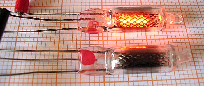
Now the good stuff. Philips built the ZA1002 to be a switching tube, not an indicator, and every design choice in it exists to widen and stabilise the hysteresis window. Its geometry is coaxial rather than the neon’s two close-spaced electrodes: a central molybdenum cathode rod sits inside a cylindrical mesh anode, and the mesh is doing real work. During manufacture the cathode is deliberately sputtered; molybdenum deposits through the mesh holes onto the tube wall in a controlled getter pattern, which both cleans up the gas and dramatically reduces the tube-to-tube variation that plagues indicator neons. The result Dekker measured across seven ZA1002 tubes is worth quoting in full, because it is the whole reason to want them:
Table 1 — whole reason to want them
| ZA1002 sample | Vs (V) | Vm (V) |
|---|---|---|
| 1 | 169.1 | 105.0 |
| 2 | 171.0 | 105.2 |
| 3 | 170.5 | 105.0 |
| 4 | 170.0 | 104.8 |
| 5 | 171.0 | 104.9 |
| 6 | 170.0 | 104.9 |
| 7 | 171.0 | 105.2 |
That is a maximum spread of about 2 V in Vs and 0.5 V in Vm across the whole batch —
and a Vs−Vm window of roughly 60–65 V on every one of them. Set that beside the
indicator neon’s 12 V average window and tube-to-tube overlap and the contrast is not subtle:
the ZA1002 hands you a window five times wider with a spread an order of magnitude tighter. A
ring built from these is forgiving — the transfer-bias floor and ceiling of Vol 4 sit far
apart, one set of resistor values comfortably covers the batch, and you may not need to bin at
all. In the language of Vol 1, this is Path 3: reliability over authenticity-of-the-cheap-lamp
challenge.
The second thing Philips built in is priming. A tiny quantity of tritium in the
envelope emits a steady drizzle of beta particles that keep the gas lightly ionised, so the
tube’s statistical breakdown delay — the random lag between reaching Vs and actually
striking — collapses to less than 1 ms for a 10–20 V overvoltage. That is what makes a
switching tube fast and certain where a bare neon dithers, and it is why switching tubes never
suffer the dark-effect erraticism of §3.2: their priming is radioactive and constant, not
photo-electric and ambient.
The ZA1001 is the sibling of the same family, best known as the octave-divider tube in the
Philips Philicorda organ, where banks of them divide a top-octave oscillator down through
the lower octaves. Vol 6 tells that story and the sibling ../Philicorda/ project dissects the
instrument; for tube-selection purposes the point is simply that the ZA100x family are the
purpose-built neon switches, and that a real commercial product shipped tens of thousands of
them doing exactly the frequency-dividing job this series is about.
3.3.1 The decayed-tritium trap in old NOS switching tubes
There is one cruel catch, and it is a direct consequence of the very priming that makes these
tubes so good. Tritium has a half-life of about 12.3 years. A ZA1002 pulled from a 1960s
production run has therefore lost almost all of its priming: sixty years on, roughly
(1/2)^(60/12.3) ≈ 1/30 of the original tritium remains (Dekker’s own page quotes about one
sixty-fourth) — and a tube that is “hardly primed” behaves like an unprimed one. What Dekker
actually observed is the tell-tale symptom: a NOS ZA1002 that should strike cleanly at
about 170 V instead strikes randomly at anything from 170 V up to 220 V, tube by tube and
strike by strike, because without priming it must wait for a chance ionising event before it
breaks down. The wide, repeatable window that was the whole selling point is undermined by an
erratic, unrepeatable striking delay and a wandering effective Vs.
The practical upshot: do not assume a NOS switching tube performs to its datasheet. Measure it (§3.5) exactly as you would a bulk indicator neon, watch specifically for erratic or elevated striking, and be prepared to provide external priming — ambient light won’t help a metal-electrode switching tube much, but a keep-alive glow, a nearby permanently-lit lamp, or even accepting a higher supply headroom can restore reliable striking. Vol 7 treats priming as a first-class drift mitigation. The irony is worth savouring: the fresh ZA1002 is the best tube in this volume, and the aged one can be, in one specific respect, worse-behaved than a humble NE-2 that never relied on radioactivity in the first place.
⚠ These tubes contain a (small, sealed, low-activity) radioactive source. Intact, a tritium switching tube is harmless — the beta particles don’t penetrate the glass. Don’t break the envelope, don’t machine or grind one, and dispose of a shattered tube sensibly rather than inhaling the contents. Handle NOS stock as glassware, not as hazmat, but respect the label.
3.4 Trigger tubes — the three-electrode cousins
A trigger tube adds a third electrode — a trigger or starter — to the cold-cathode
gap. Left alone, the main anode-to-cathode gap sits below its own striking voltage and stays
dark; a small pulse applied to the trigger electrode ionises a local region and fires the
main gap, which then latches on (glowing, carrying its main current) until the anode voltage is
pulled below Vm. In other words a trigger tube is a gas-filled latch or relay —
electrically a close relative of the hot-cathode thyratron, but cold and low-power. The
Z70U (and its subminiature cold-cathode trigger-tube relatives — the Z70W, the
Sylvania/Philips 5823, and their kin) is the archetype an experimenter is most likely to
meet.
Where do they fit in a ring counter? Not, usually, as the counting stages — the beauty of the two-electrode ring (Vol 4) is that the counting, memory and display are all one bit of glowing gas, and a trigger tube’s third electrode is an extra thing to drive at every stage. Their place is at the edges: as a clean, well-defined input trigger or carry element that fires on a small pulse and delivers a crisp, latched output — the kind of job the PA3FWM clock ended up needing an extra “buffer” neon for (Vol 7), and the kind of steering the original 1950 Manley–Buckley ring did with germanium diodes (Vol 4). A trigger tube gives you a deliberate, pulse-fired switch with a controlled striking threshold, which is exactly what you want for injecting the input pulse or handing a carry to the next decade, and it does it with a far larger and more repeatable margin than a bare indicator neon can. Dance’s Electronic Counting Circuits treats trigger-tube logic at length; for this series, log them as the three-electrode option to reach for when you need a commanded strike rather than a self-transferring one.
3.5 A comparison table — what you are actually choosing between
Everything above collapses into one table. The numbers are the grounded figures used throughout this series (Dekker’s measurements for the neon average and the ZA1002 batch; nominal datasheet ranges elsewhere); treat the indicator-neon rows as typical, expect spread and the ZA1002 row as measured, tight.
Table 2 — 3.5 A comparison table — what you are actually choosing between
| Device | Electrodes | Vs | Vm | Vs−Vm window | Priming | Spread / consistency | Availability today |
|---|---|---|---|---|---|---|---|
| NE-2 / NE-2H / NE-51 indicator neon | 2 (Ba-coated) | ~65–110 V (nom. ~90 V) | ~55–60 V | ~12–20 V | photo-electric (ambient light) | large, tube-to-tube overlap | plentiful, cheap, new |
| Soviet IN-3 (ИН-3) indicator neon | 2 (Ba-coated) | ~73–92 V (binned) | ~38–53 V (binned) | ~35–40 V binned* | photo-electric | large — bulk NOS, must bin | plentiful surplus, cheap |
| Philips ZA1002 switching tube | 2 (coaxial, Mo rod + mesh) | ~170 V (169.1–171.0 measured) | ~105 V (104.8–105.2) | ~60–65 V | tritium (<1 ms strike) | very tight (~2 V Vs, ~0.5 V Vm) | NOS only, scarce, priming decayed |
| Philips ZA1001 switching tube | 2 (family sibling) | (family — large window) | — | large | tritium | tight | NOS only (Philicorda parts) |
| Z70U-class trigger tube | 3 (adds trigger) | main gap set by trigger pulse | ~depends on type | large, commanded | often primed | good, but a 3-terminal part | NOS, modest availability |
| Dekatron (see Vol 5) | many (anode + 10 main + guides) | anode ~400–475 V | — | integrated ring | primed | per-tube, purpose-built | NOS, pricier |
*The IN-3 Vs−Vm figure is the span across Luc Small’s three binned clusters (§3.6);
within any one cluster the usable per-tube window is a good deal tighter than the raw
population, which is the entire point of binning.
The one-sentence reading of that table: the ~12–20 V window of a common indicator neon is marginal and must be earned back by binning; the ~60 V window of a fresh ZA1002 is luxurious and nearly design-proof — but the ZA1002 is scarce and its priming has decayed, so in practice most builders take the cheap tube and do the work. That work is §3.7.
3.6 Sourcing NOS tubes in 2026 — what to buy and what to watch for
None of these devices is in production. Everything you build with is new-old-stock, and the sourcing reality shapes the project as much as the physics does.
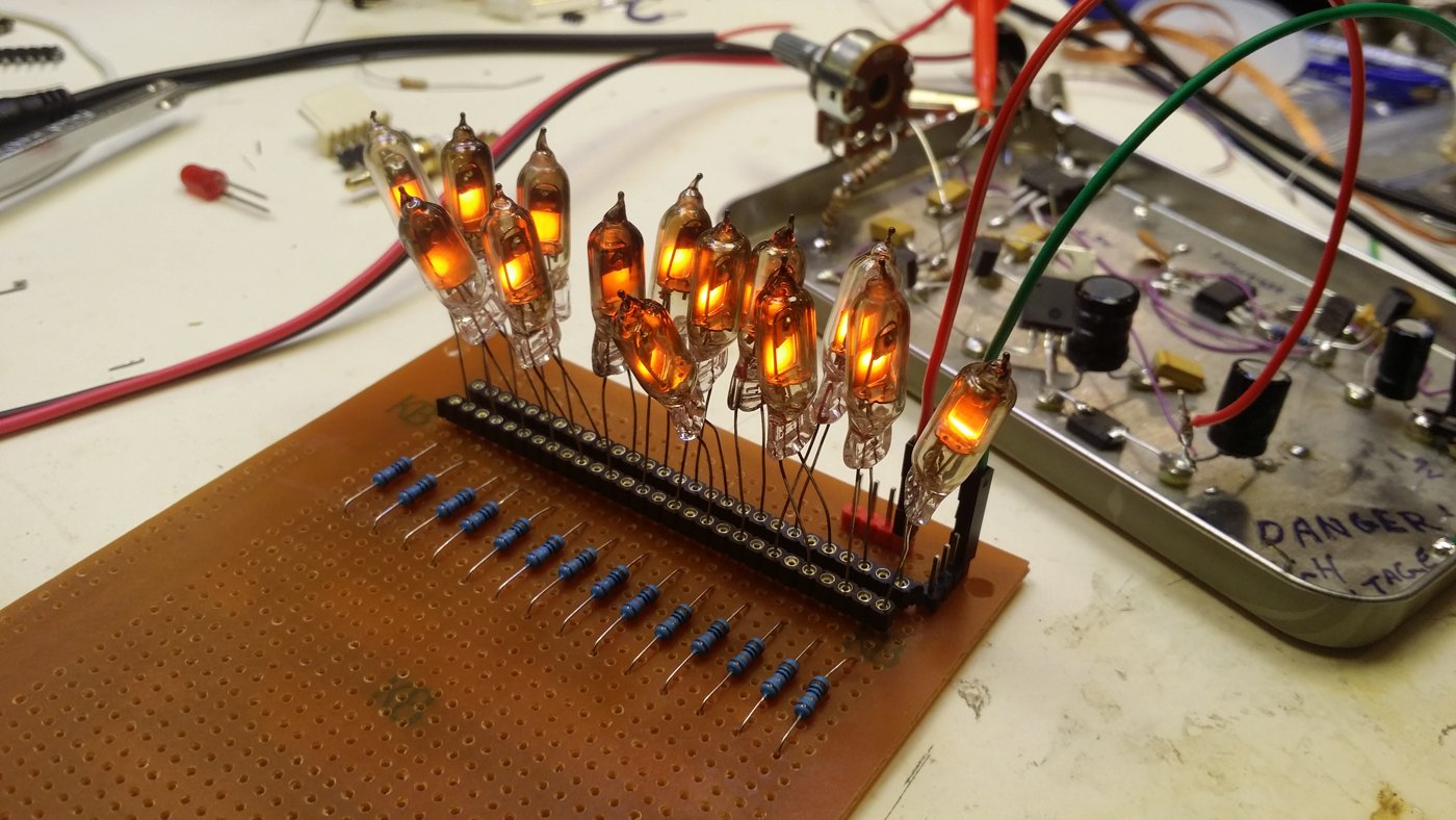
- Indicator neons (NE-2 / IN-3). The easy path. New NE-2s are still made and sold by the bag; Soviet IN-3 turn up in bulk lots of 50–200 on eBay and surplus sites, most often from Ukrainian and Eastern-European sellers, for pocket change per tube. Buy far more than you need — a ring wants ten or twelve good matched tubes, and after burn-in and binning you may keep only a third of a lot in your best cluster. Luc Small bought 200 to build one ten-stage ring, and that ratio is realistic. Watch for: mixed date codes and factories in one “lot” (more spread), cracked or gassy tubes (won’t strike cleanly, or strike pink/blue instead of orange), and sellers who photograph one tube and ship you a grab-bag.
- Switching tubes (ZA1001 / ZA1002). The scarce path. These surface individually or in small lots from tube specialists and estate sales, at real money per tube. Buy them if you can find them and you value reliability, but budget for the decayed-tritium problem of §3.3.1: assume every tube older than a couple of half-lives strikes high and erratically until you have measured it, and don’t pay switching-tube prices for a tube you can’t test on arrival.
- Trigger tubes (Z70U-class). Modest availability from the same tube-specialist channels; cheaper than switching tubes, three leads to deal with. Fine to stock a few for input/carry experiments.
- Dekatrons — a different market again; Vol 5 covers GS10/GC10B/OG-4 sourcing.
Whatever you buy, the invariant is the same: you cannot trust a tube’s markings, you can only trust your own measurement. A “matched set” from a seller means a set that looked similar to someone with no bench; a matched set from you means tubes you have burned in and measured into a cluster. That is the next section.
3.7 The binning procedure — burn in, measure, cluster
Binning is the single highest-leverage thing you will do to a box of indicator neons, and it is
not hard — it is just patient. The workflow has three stages: burn in to stabilise the
tubes, measure each tube’s Vs and Vm, and cluster the survivors into ranks you can
each design a ring around. Vol 11 turns this into a permanent bench jig with a socket bank and an
hour-meter; here is the procedure itself.
3.7.1 Burn-in first — never measure a cold tube
A fresh or long-dormant neon does most of its lifetime drift in its first hours of running, as the gas cleans up against the electrodes. Measure it cold and you will bin it against numbers it will not keep. So run every tube at roughly its rated current for a good long soak before you measure — Luc Small used 48 hours; PA3FWM burned tubes in before characterising them; Dekker aged his at about 1 mA on AC. A simple burn-in is a current-limited HV rail feeding a bank of sockets, each tube in series with its own resistor, left glowing for a day or two (Vol 11 builds exactly this). The soak also weeds out infant-mortality tubes — anything that won’t strike, strikes the wrong colour, or flickers is culled here, before it wastes a slot in your ring.
3.7.2 Measuring Vs and Vm — the slow-ramp method
The measurement rig is almost trivial, which is the beauty of it: a variable HV supply, a series current-limiting resistor (~100 kΩ is fine), a socket for the tube under test, and a voltmeter across the tube (a second meter on the supply is convenient). The whole method rests on one fact from Vol 2: before the tube strikes, no current flows, so there is no drop across the series resistor and the tube sees the full supply voltage.
The ramp procedure, tube by tube:
- Start the supply comfortably below striking — for indicator neons, around 65 V.
- Raise the supply slowly. Because no current is flowing yet, the tube voltage tracks the supply exactly.
- The instant the tube strikes (it lights), read the voltage. That is
Vs. On Luc’s rig this is simply the supply reading at the moment of ignition. - Current now flows and the tube clamps to its glow drop; the series resistor absorbs the difference. The voltage across the tube is now the normal-glow maintaining voltage.
- Lower the supply slowly until the glow dies. The across-tube reading just before it
extinguishes is
Vm. - Record the
(Vs, Vm)pair against a tube number, and move on.
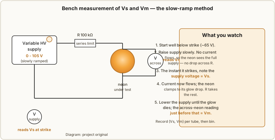
Luc built his ramp supply to cover roughly 65–105 V, which brackets the whole IN-3 population,
and used two voltmeters so he could watch supply and tube voltage at once. A few practical notes:
ramp slowly — the strike is the event you’re timing, and a fast ramp overshoots Vs; do the
measurement under consistent lighting, because the dark effect will move an indicator neon’s
Vs by volts between a bright and a dim bench; and if a tube strikes erratically or at a wandering
voltage, flag it — for an indicator neon that’s a cull, for a NOS switching tube it’s the
decayed-tritium signature of §3.3.1.
3.7.3 Clustering — Luc Small’s three IN-3 bins as the worked example
With a (Vs, Vm) pair for every survivor, sort them. Plot Vs (a histogram or even just a sorted
list) and the population will usually fall into natural groups separated by gaps — those groups are
your bins. Each bin is a sub-population tight enough that a single Rcat/Ra design covers it; you
then build one ring per bin, not one ring spanning the whole ragged population.
Luc Small’s real numbers are the canonical worked example. From 200 IN-3 he characterised 50 and, after the 48-hour burn-in, sorted them into three clusters:
Table 3 — after the 48-hour burn-in, sorted them into three clusters
| Cluster | Count | Vs range | Vm range | Vs−Vm (typical) |
|---|---|---|---|---|
| Lower | 14 | 73–77 V | 38–42 V | ~35 V |
| Middle | 8 | 82–86 V | 42–46 V | ~40 V |
| Upper | 11 | 88–92 V | 48–53 V | ~40 V |
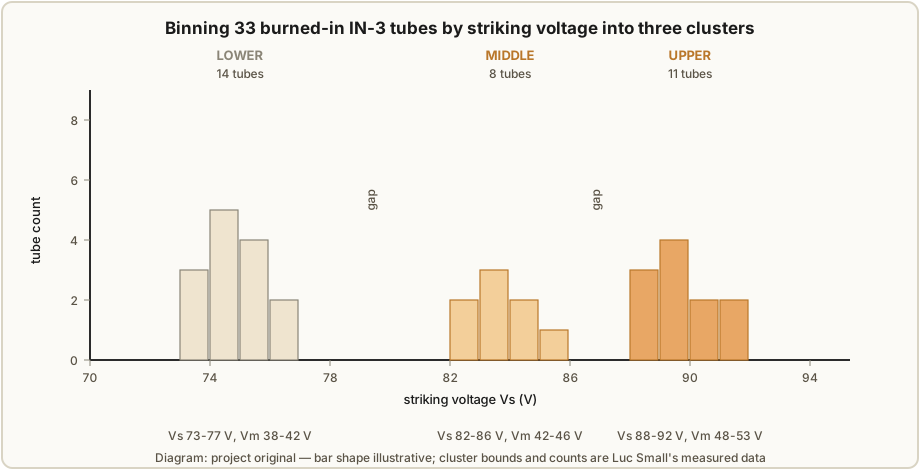
Notice what binning bought him. The raw population spanned Vs from 73 V to 92 V — a 19 V spread
that, mixed together, would make the ring-counter algebra of Vol 4 impossible (one tube’s striking
voltage sitting near another’s, no room to place the transfer bias). Split into the Lower bin,
the spread collapses to about 4 V of Vs (73–77 V) around a clean ~35 V window — and that is a
population a single ring design can herd. Those 33 clustered tubes give a 14-strong Lower cluster —
enough for a ten-stage ring with matched spares. This is the whole argument for binning in one
before/after picture: an impossible population becomes three easy ones.
3.7.4 Feeding the cluster into the ring design
The bin you choose sets the numbers Vol 4 will crunch — so binning isn’t just quality control, it’s
the front end of the design. Once a cluster is picked, its average Vs and Vm drop straight into
the transfer-bias and resistor equations. For Luc’s Lower cluster (Vs ≈ 75 V, Vm ≈ 40 V) the
worked result — which Vol 4 derives in full and Vol 13 builds — was a ring on a 150 V supply, a
target lamp current Inom of 800 µA, a cathode resistor Rcat of 18 kΩ (the equation gives
16 875 Ω), an anode resistor Ra of 120 kΩ (calculated 120 625 Ω), and a 100 nF / 250 V
coupling/pulse capacitor switched by an MPSA42 high-voltage transistor, pulsed by a 555 (a
~110 ms monostable one-shot for single-stepping, a ~12.5 Hz astable for free-running). Every one of
those numbers traces back to this cluster’s Vs/Vm — pick the Middle or Upper bin instead and
the resistors and supply shift accordingly. That is why the sequence is tubes → burn-in → measure →
bin → then design, and never the other way around.
3.8 So which tubes should you use?
For most builders, most of the time: buy a bulk lot of indicator neons — Soviet IN-3 for the authentic bulk-and-bin experience, or plain NE-2 — over-buy by 3× or more, burn them in, measure them with the slow-ramp rig, and build from your tightest cluster. It is cheap, it is available, and the binning work is genuinely satisfying. If you can find and afford fresh-enough ZA1002 switching tubes and you value reliability over the cheap-lamp challenge, buy them and enjoy the luxurious ~60 V window — but test every one on arrival for the decayed-tritium erratic-strike problem, and don’t pay for a datasheet number you can’t measure. Keep a few trigger tubes on the shelf for input and carry experiments where you want a commanded strike. And if what you really want is a numbered decade display rather than a raw ring, skip ahead — the dekatron of Vol 5 packs the whole ring into one envelope. Whichever you choose, the discipline is identical and non-negotiable: a tube is only as good as your own measurement of it, and the box of surplus lamps on your bench is a population to be characterised, not a bag of parts to be trusted.
References
- R. Dekker (dos4ever), “A Neon Ring Counter” / Ring Counter Variations — https://www.dos4ever.com/ring/ring.html — ZA1002 measured
Vs/Vmbatch, sputtered-Mo/mesh construction, tritium priming and <1 ms strike, the 12.3-year half-life decayed-tritium erratic-striking problem, the 21-tube indicator-neon average window (68.8 V / 56.9 V), and the binning approach. - L. Small, “Neon Ring Counters” (2016) — https://lucsmall.com/2016/10/08/neon-ring-counters/ — the 200× IN-3 build, 48-hour burn-in, the slow-ramp
Vs/Vmmeasurement rig (65–105 V), the three clusters (Lower/Middle/Upper with counts and ranges), and the Lower-cluster ring values fed into the design. - P.-T. de Boer (PA3FWM), “A clock using neon lamps as logic elements” — https://www.pa3fwm.nl/projects/neonclock/ — indicator-neon ageing/drift and the dark-effect priming failure (fixed with LEDs), and the buffer-lamp carry practice referenced here.
- J. B. Dance, Electronic Counting Circuits (London: Iliffe / New York: American Elsevier, 1967) — in the site’s reference library — the canonical treatment of cold-cathode indicator neons, switching tubes, trigger tubes and dekatrons underpinning this volume.
- Manley & Buckley, “Neon Ring Counter,” Electronics, January 1950 — the original diode-steered ring counter (context for trigger-tube steering).
Comments (0)