Neon Ring Counters · Volume 2
How a Neon Lamp Works
Glow discharge, striking vs. maintaining voltage, negative resistance, and the hysteresis that makes a bulb remember
Everything in this series — the ring counters, the dekatrons, the octave dividers, the
neon-logic clock — is built on a single, slightly improbable fact about a two-cent
indicator lamp: a neon glow lamp does not turn on and off at the same voltage. Push the
voltage across it up slowly and nothing happens; the gas stays dark, the lamp draws a
current you would need a sensitive meter even to see, and it behaves like a very good
insulator. Then, at a well-defined striking voltage Vs, the gas breaks down all at
once, a wisp of orange light appears against the negative electrode, and the lamp becomes a
conductor. Now turn the voltage back down and the light does not go out at Vs — it hangs
on, stubbornly, all the way down to a much lower maintaining voltage Vm, and only there
does it finally extinguish. Between those two voltages the lamp is bistable: lit or dark
depending entirely on what happened to it a moment ago, not on the voltage you are applying
right now. That gap — the hysteresis — is memory, it is switching, and it is the whole
reason a bag of pilot lamps can be made to count. This volume is the physics foundation the
rest of the dive leans on, so it is worth going slowly. We will look at the lamp as a gas
device, at why striking and maintaining voltages differ, at the full voltage–current curve
with its notorious negative-resistance region, at how a single series resistor tames that
region into a usable operating point, and then at the two circuits that fall straight out of
the physics: the bistable memory cell and the relaxation oscillator. We finish with the two
things that will bite you in practice — the lamp’s photosensitivity, and the deionisation
time that caps the whole technique at roughly a kilohertz.
2.1 The device: cold cathode, low-pressure neon
A neon indicator lamp is mechanically almost nothing. Inside a small glass envelope sit two electrodes a millimetre or two apart — in the ubiquitous NE-2 they are two parallel wires or small plates — surrounded by a low-pressure gas fill. There is no heater and no thermionic cathode: this is a cold-cathode device, and that single fact separates it from the vacuum tubes of the same era. A triode or a rectifier boils electrons off a hot filament; a neon lamp gets its electrons by tearing them out of gas atoms with the electric field alone. That makes it rugged, instant-on, and cheap, but it also means the physics that governs it is the physics of gas discharge, not of vacuum-thermionic emission.
The fill is mostly neon, chosen for its low breakdown voltage and its characteristic orange-red glow at roughly 585–640 nm, but a pure-neon lamp would strike at an inconveniently high and erratic voltage. Almost all practical indicator neons therefore use a Penning mixture — neon with a small percentage of argon (a fraction of a per cent is enough). The argon atoms have a metastable excited state whose energy sits just above neon’s ionisation energy, so an excited argon atom colliding with a neon atom can ionise it. This “Penning effect” lowers and stabilises the striking voltage substantially. The gas sits at low pressure, typically a few tens of torr (very roughly a tenth of atmospheric); the pressure, the electrode spacing, and the gas mix together set where on Paschen’s curve the lamp operates and therefore what its striking voltage will be. The cathode of an indicator neon is usually barium-coated to lower its work function, which both reduces the maintaining voltage and — importantly for us later — makes the lamp mildly photosensitive.
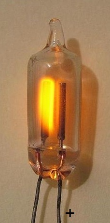
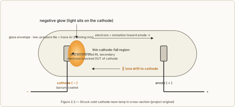
When the lamp strikes, the light does not fill the tube uniformly. The glow forms a thin, bright sheath hugging the cathode — the negative electrode — because that is where the action is. A cold-cathode discharge sustains itself by secondary emission: positive ions, accelerated across a thin high-field region right at the cathode surface (the cathode fall), slam into the cathode and knock loose fresh electrons. Those electrons are then accelerated away, ionise more gas atoms by collision on their way to the anode, and the resulting new ions drift back to bombard the cathode again. It is a self-sustaining chain, but only if enough of the voltage is concentrated in that cathode-fall region. This is why the visible glow sits on the cathode and why, in a lamp fed AC, both electrodes appear to glow — each takes its turn as cathode. In a ring counter, incidentally, this asymmetry is a feature: it tells you at a glance which electrode is which.
2.2 Why striking and maintaining voltages differ
The single most important idea in this volume is that Vs > Vm, and the reason is worth
stating plainly because it justifies everything downstream. Striking and maintaining
are two different physical jobs, and they cost different amounts of voltage.
To strike the lamp — to go from a dark, essentially non-conducting gas to a self-sustaining
discharge — you have to bootstrap the ionisation from almost nothing. In the dark gas there
are only a handful of stray free electrons (from cosmic rays, background radioactivity, or
photo-emission — more on that later). To get a discharge going, the field must accelerate one
of those rare electrons hard enough that it ionises an atom before it is lost, and the
resulting electron must do the same, so the ionisation avalanches faster than charges are
swept away. Building that avalanche from a cold start, against a gas that has no reservoir of
ions to help, takes a comparatively high field — hence a high striking voltage Vs.
To maintain the lamp is a much easier job. Once the discharge is running, the gas near the
cathode is already full of ions and electrons; there is a standing population of charge
carriers, the cathode is already being bombarded and is already emitting secondaries, and the
cathode-fall region has organised itself into an efficient ion-accelerating structure. Keeping
that going only requires enough voltage to replace the carriers lost to recombination and to
the walls each instant — which is less than it took to create the discharge from scratch.
Hence a lower maintaining voltage Vm. Drop the voltage below Vm and the loss rate
finally exceeds the generation rate, the carrier population collapses, and the lamp goes dark.
So the hysteresis is not a manufacturing imperfection to be trimmed out — it is intrinsic to
the difference between igniting an avalanche and feeding an established one. For a common
barium-cathode indicator neon of the NE-2 / IN-3 class, Vs sits somewhere in the region of
65–110 V (nominally around 90 V) and Vm around 55–60 V, so the usable window
Vs − Vm is only about 12–20 V. That is a marginal gap — Dekker measured an average of
about 68.8 V striking against 56.9 V maintaining on a batch of ordinary neons, a difference of
only ~12 V — and Vol 3 is largely about coping with how small and how variable it is. Purpose-built
switching tubes like the Philips ZA1002 deliberately engineer a much wider window (about
170 V striking against 105 V maintaining, a luxurious ~60 V gap) precisely because a
wide Vs − Vm makes reliable counting so much easier. The whole tube-selection story of Vol 3,
and the design-margin mathematics of Vol 4, are ultimately about this one number.
2.3 The voltage–current curve, region by region
If you very carefully sweep the current through a gas discharge tube from near zero up toward an ampere and plot the voltage across it, you trace out one of the classic curves of gas-discharge physics. It is not monotonic, and the part that matters most to us actually slopes the wrong way. Because the current spans many orders of magnitude, it is conventional to plot current on a logarithmic axis.
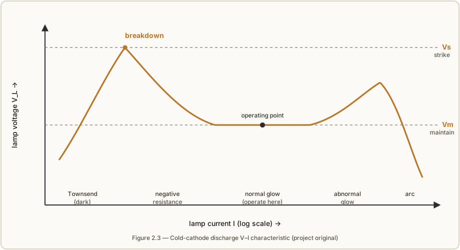
Walking along the curve from the left:
- Townsend (dark) region. At low voltage the gas conducts a tiny current — picoamps to microamps — carried by the few stray charges present, multiplied a little by the field. There is essentially no light. The tube looks like a very large, very nonlinear resistance. This is the “off” state a ring-counter lamp sits in when it is not the lit one.
- Breakdown at
Vs. Raise the voltage to the striking voltage and the avalanche described in §2.2 runs away. The current jumps abruptly by orders of magnitude and the gas lights up. This is the vertical cliff on the curve — the transition is effectively instantaneous compared with any circuit timescale we care about. - Negative-resistance transition. Immediately after breakdown, something counter-intuitive happens: as the current increases, the voltage across the tube falls. Over this stretch the device has a negative differential resistance — dV/dI is negative. The discharge is becoming more efficient as it establishes itself, needing less voltage to carry more current. This falling region is exactly what makes a gas tube able to oscillate and to switch regeneratively; it is also what makes it impossible to operate stably without a series resistor (§2.4).
- Normal glow plateau (≈
Vm). The voltage bottoms out and then stays remarkably flat — nearly constant at close to the maintaining voltage — over a wide range of current. Physically, as you demand more current the glow simply spreads to cover more of the cathode area while the current density and the cathode-fall voltage stay put; only when the glow has covered the whole cathode does the voltage have to rise again. This flat plateau is the useful operating region: it is why a neon lamp makes a passable (if crude) voltage reference, and it is where every indicator lamp and every ring-counter stage is meant to sit. - Abnormal glow. Once the glow covers the entire cathode, pushing still more current forces the cathode-fall voltage up again — the curve turns and climbs. The lamp is being driven harder than intended; run here for long and cathode sputtering accelerates ageing.
- Arc. At high enough current the cathode heats until it begins thermionic emission, the cathode fall collapses, the voltage drops steeply, and the discharge transitions to a low-voltage, high-current arc. In a little indicator neon this is destructive — it is the regime that ends the tube’s life — and the series resistor exists partly to make sure you never get here.
For our purposes the whole design problem is: strike on the cliff at Vs, then live on the
flat plateau near Vm, and never wander into the abnormal-glow or arc regions. The next
section is how a single resistor accomplishes exactly that.
2.4 Series resistance sets the operating point
A device with a negative-resistance region cannot be driven from a stiff voltage source and
left to its own devices. If you connect a neon lamp directly across a supply equal to Vs, at
the instant it strikes the falling characteristic means the current is limited only by the
lamp’s own tiny internal resistance and the source impedance — the current runs away toward the
arc region and the lamp destroys itself. The cure is a series resistor R, and it is not
optional: essentially every neon-lamp circuit ever built has one.
The trick is a load line. With a supply V and a series resistor R, the voltage across
the lamp V_L and the current I through it must satisfy Kirchhoff’s law,
V = V_L + I·R ⟹ I = (V − V_L) / Rwhich on the V–I plane of Figure 2.3 is a straight line: it hits the voltage axis at V_L = V
(zero current) and the current axis at I = V/R (zero lamp voltage), with slope −1/R. The
lamp’s actual operating point is where this load line crosses the device curve. Choose R
large enough and the load line crosses the curve out on the gentle normal-glow plateau, at a
modest current where the tube is happy; choose R too small and the crossing marches up into
abnormal glow or the line misses the plateau entirely and heads for the arc.
Concretely: pick the lamp current you want, call it I_nom, decide the lamp will drop about
Vm while lit, and solve for the resistor,
R ≈ (V − Vm) / I_nomFor a garden-variety NE-2 on a 120 V supply, wanting about 0.5 mA of lamp current with a
maintaining drop near 60 V, that gives R ≈ (120 − 60) V / 0.5 mA = 120 kΩ — which is exactly
why you so often see a neon indicator sitting behind a resistor of a few tens to a few hundred
kilohms. In a ring counter the same idea reappears twice over: an anode resistor Ra
sets the overall stage current, and each stage’s own cathode resistor Rcat both limits
current and develops the transfer bias that steers the glow — the full design mathematics is
Vol 4’s subject, but the governing idea is this one: the resistor, working against the
device’s own curve, is what pins the operating point down on the stable plateau.
⚠ A reminder that starts here and runs through the whole series: the rails that make neon lamps strike are ~100–450 V DC, and a reservoir capacitor stays charged after power-off. That is lethal. Vol 14 is the full safety discipline; treat every rail as live until you have proven it discharged with a meter.
2.5 The hysteresis window as memory
Now put §2.2 and §2.4 together and the bistable memory cell falls out for free. Suppose the
lamp sits behind a resistor on a fixed supply V chosen to lie between Vm and Vs — for
an NE-2, somewhere around 70–85 V. What state is the lamp in?
The answer is: it depends on its history. If the lamp is currently dark, the voltage
across it is essentially the full supply V, which is below Vs, so it cannot strike — it
stays dark. If the very same lamp is currently lit, it is holding its voltage down near Vm,
and since V is above Vm the discharge is comfortably sustained — it stays lit. Two stable
states, same applied voltage, chosen by what came before. That is a one-bit memory cell built
from a single lamp, and it is why Dekker calls the neon tube “equivalent to a logic circuit
element with a memory.”
To write the cell you nudge it across a threshold. A brief positive pulse that lifts the
lamp voltage momentarily above Vs will strike it, and it then latches lit when the pulse
goes away (because V > Vm). A brief negative pulse — or a momentary collapse of the supply
rail — that drops the voltage below Vm will extinguish it, and it then latches dark (because
V < Vs). Set and reset, from a lamp and a resistor. This is the primitive that the ring
counter of Vol 4 chains together: an input pulse collapses the common rail, extinguishing the
lit stage, and the coupling network arranges for a particular neighbouring stage to be the
one nudged past Vs on recovery — so the single lit dot always advances one place, and always
in the same direction. Memory plus a steering network is a shift register; a shift register
wired in a circle is a ring counter.
The width of that memory window, Vs − Vm, is your entire noise and design margin. With a
switching tube’s 60 V window you can be sloppy; with an NE-2’s 12–20 V window — and with that
window varying from lamp to lamp across a bag of surplus neons — you must bin the lamps
and centre the bias carefully, which is the recurring practical theme of Vols 3, 7, and 11.
2.6 The neon relaxation oscillator
The most satisfying thing you can build from one lamp, one resistor, and one capacitor is a
relaxation oscillator — the “hello world” of gas-discharge electronics, and the fastest way
to convince yourself that the hysteresis is real. It is also the circuit at the heart of the
dekatron’s guide drive, of countless neon flashers, and (in spirit) of the timebase pulses that
clock a ring. The schematic could not be simpler: a supply V, a series resistor R charging a
capacitor C, and a neon lamp connected directly across C.
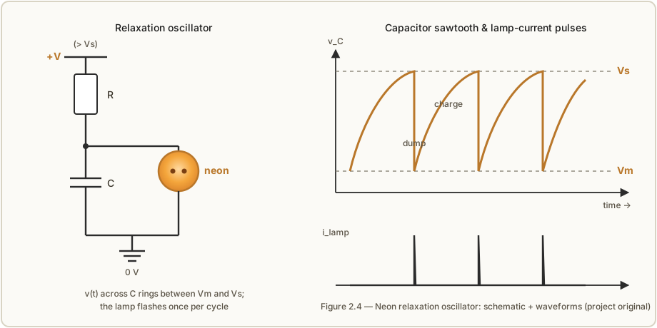
Here is the cycle. At switch-on the capacitor is empty and the lamp is dark (an open circuit,
drawing negligible current), so C charges toward V through R on the usual exponential.
The voltage across the cap — and therefore across the lamp — climbs until it reaches Vs. The
lamp strikes. Now it is a low resistance, and it rapidly dumps the capacitor’s charge — the
cap discharges through the lit lamp far faster than R can refill it — until the voltage falls
to Vm, at which point the lamp can no longer sustain itself and extinguishes. The cap is now
back at Vm, the lamp is dark again, and R begins recharging it toward V for the next
cycle. The result is a sawtooth across the capacitor — a slow exponential rise from Vm to
Vs, then a near-vertical fall — and a sharp current pulse through the lamp once per cycle,
each accompanied by a visible flash. For this to oscillate at all you need V > Vs; if the
supply cannot reach the striking voltage, the cap just charges up and sits there, dark, forever.
2.6.1 Deriving the period
The period is set entirely by the charging phase, because the discharge is comparatively
instantaneous. During charging the lamp is dark and out of the picture, so we have a plain
RC circuit charging from an initial voltage Vm (where the last discharge left the cap)
toward the supply V:
v(t) = V − (V − Vm)·e^(−t / RC)Here v(t) is the capacitor voltage, t is time since the last firing, R is in ohms, C
in farads, so RC is the time constant in seconds. The lamp fires when v(t) reaches the
striking voltage Vs. Set v(T) = Vs and solve for the period T:
Vs = V − (V − Vm)·e^(−T / RC)
(V − Vs) = (V − Vm)·e^(−T / RC)
e^(−T / RC) = (V − Vs) / (V − Vm)
Taking the natural log of both sides and tidying the signs gives the standard neon relaxation-oscillator period:
T ≈ R·C · ln( (V − Vm) / (V − Vs) )and the frequency is f ≈ 1 / T. Every term has a clear meaning: (V − Vm) is how far
above the “reset” voltage the supply pulls, (V − Vs) is the (smaller) gap still remaining
when the cap has climbed to the firing point, and their ratio inside the logarithm is the
fraction of the charging curve the cap must traverse each cycle. Note what the formula does
not contain: any strong dependence on the exact shape of the discharge, because we assumed
the dump is instant. In reality the discharge takes a small but finite time (§2.8), which adds
a little to T and matters at high frequencies; at the leisurely rates a visible flasher runs,
it is negligible.
2.6.2 A worked NE-2 example
Take a real NE-2 and real parts. Suppose after binning we know this lamp strikes at
Vs = 90 V and maintains at Vm = 60 V, and we run it from a V = 120 V supply through
R = 1 MΩ charging C = 100 nF (0.1 µF). Then:
V − Vm = 120 V − 60 V = 60 V
V − Vs = 120 V − 90 V = 30 V
ratio  = 60 / 30 = 2
ln(2)  ≈ 0.693
RC     = 1 MΩ × 100 nF = 1×10⁶ Ω × 100×10⁻⁹ F = 0.1 s
T      ≈ 0.1 s × 0.693 ≈ 0.069 s ≈ 69 ms
f      ≈ 1 / 0.069 s ≈ 14 Hz
So this lamp blinks about fourteen times a second — fast enough to look like a flicker, slow
enough to see. Want a stately once-per-second beacon instead? The period scales linearly with
both R and C, so multiply RC by roughly ten — say R = 2.2 MΩ and C = 0.47 µF,
giving RC ≈ 1.03 s and T ≈ 1.03 s × 0.693 ≈ 0.72 s, about 1.4 Hz. Three design cautions
fall straight out of the equation. First, V must exceed Vs or the argument of the log
goes to infinity (the cap never reaches firing) and there is no oscillation. Second, the
frequency is exquisitely sensitive to how close V sits to Vs: as V approaches Vs from
above, (V − Vs) shrinks, the logarithm blows up, and the period lengthens dramatically and
becomes very sensitive to supply drift and to the lamp’s own Vs wander — which is why a neon
relaxation oscillator is a charming toy but a poor precision timebase. Third, the charging
resistor must be large enough that the lamp genuinely extinguishes each cycle: if R is so
small that it can by itself supply more than the lamp’s maintaining current, the cap never falls
below Vm, the lamp stays lit, and the oscillation stops dead. In practice keep R up in the
hundreds-of-kΩ to megohm range for an NE-2. Use a low-leakage, stable capacitor here, too —
Vol 10 explains why an electrolytic or a high-K ceramic will make the period drift and jitter.
2.7 Photosensitivity, the dark effect, and priming
Here is the property that turns an otherwise-tidy story into a real engineering headache, and it follows directly from §2.2. Striking requires a first free electron to start the avalanche, and in a truly dark, unirradiated tube those seed electrons are genuinely scarce — they trickle in only from cosmic rays and background radioactivity, at random. So the striking voltage a neon lamp actually shows depends on how many seed electrons are around, and that in turn depends on the light and radiation falling on it.
In the light, the barium cathode photo-emits electrons — the same photo-electric effect
that made the lamp mildly light-sensitive in the first place — so there is always a healthy
supply of seeds, the lamp strikes promptly and at a repeatable Vs. Put the same lamp in the
dark and the seeds dry up: Vs rises, and worse, it becomes erratic and slow — the
lamp may hesitate for milliseconds, tens of milliseconds, or refuse to strike until the voltage
has been pushed well above its nominal Vs. This is the dark effect, and it is exactly the
failure Pieter-Tjerk de Boer hit with his neon-logic clock (Vol 12): in a darkened room the
lamps would not prime reliably, and the fix was as low-tech as it sounds — a couple of small
blue LEDs left on inside the case to keep the tubes illuminated. The dark effect is not a defect
of one lamp; it is intrinsic to cold-cathode striking, and any ring counter or clock meant to
run in the dark has to reckon with it.
The general cure is priming — deliberately guaranteeing a supply of seed charges so the lamp never has to wait for a random one:
- Ambient light, or a dedicated keep-alive lamp/LED aimed at the tubes, exploits the photo-emission directly. Cheap and effective; it is what fixed the PA3FWM clock.
- A keep-alive glow. Running a tiny continuous discharge — a permanently-lit priming cell, or a low trickle current through the tube itself — keeps ions and electrons present so a full strike happens instantly and repeatably. Many purpose-built cold-cathode counting tubes include a small priming/pilot cathode for exactly this.
- Radioactive priming. The most elegant industrial solution was to seal a trace of a weak radioisotope into the tube — tritium, krypton-85, nickel-63, or a little thorium — whose steady decay sprays out charged particles that keep the gas mildly ionised at all times, in light or dark. Philips primed the ZA1002 switching tube with tritium, which gave it a strike time under a millisecond regardless of illumination. The catch is radioactive decay: tritium’s half-life is 12.3 years, so a tube built sixty-odd years ago has been through roughly five half-lives and retains only about 1/32 to 1/64 of its original priming. This is precisely why aged NOS switching tubes strike erratically today, anywhere from their rated ~170 V up to 220 V — Dekker documented exactly this decay-driven drift. Vol 3 returns to it when we talk about sourcing tubes, and Vol 7 when we talk about ageing.
The practical takeaway for any build: if reliability matters, prime your lamps — keep them lit by a little ambient or dedicated light at minimum — and never assume a tube characterised in a bright lab will behave the same in a dark enclosure.
2.8 Deionisation, recovery time, and the ~1 kHz speed ceiling
The last piece of physics is the one that sets the technique’s fundamental speed limit, and it
is the mirror image of striking. When you extinguish a lamp — drop it below Vm — the gas does
not become an insulator instantly. It takes time for the free electrons and ions to recombine or
drift to the walls and for the gas to return to its dark, un-ionised state. That interval is the
deionisation time (or recovery time), and for ordinary neon lamps it is of the order of
milliseconds — hundreds of microseconds to a few milliseconds depending on the gas, the
pressure, and the current that had been flowing.
Until deionisation is complete the tube “remembers” it was recently lit: it still has a residual population of carriers, so it will re-strike at an abnormally low voltage, or refuse to reset cleanly. In a ring counter this directly limits how fast you can clock the thing. Each transfer step requires the previously-lit stage to fully extinguish and deionise before the next input pulse arrives, otherwise the glow smears, double-steps, or fails to advance. With a millisecond-class recovery time, that puts the ceiling for cold-cathode ring counting at roughly 1 kHz — Dekker states plainly that deionisation “limits the speed of cold-cathode diode ring circuits to ca. 1 kHz.” Special cases and specially-gassed tubes push this to perhaps ~10–20 kHz; Dekker only reached around 500 kHz by abandoning gentle capacitive coupling entirely and driving the ring with fast TTL pulses through a high-voltage transistor pull-down — a very different beast from a passive neon ring.
This is not a bug to be engineered away so much as a boundary that defines the whole field. Neon counting is a low-speed, human-scale technique: it is unbeatable for a display you can watch step around a dial, for dividing a mains-derived 50 or 60 Hz tick down to seconds and minutes (Vol 6), or for a leisurely calculator or scaler — and it is simply the wrong tool above a few kilohertz, where its silicon successors take over. The ~1 kHz ceiling, the ~12–20 V window, the dark effect, and the negative-resistance curve are the four facts that shape every design decision in the rest of this series. With them in hand, we can turn in Vol 3 to the practical question they raise: given how marginal and variable ordinary neons are, which tubes should you actually buy, and how do you sort the usable ones from the rest?
References
- R. Dekker, “A Neon Ring Counter” / Ring Counter Variations — https://www.dos4ever.com/ring/ring.html (the glow-transfer physics,
Vs/Vmhysteresis, measured neon and ZA1002 values, deionisation and the ~1 kHz ceiling, tritium priming and its decay). - L. Small, “Neon Ring Counters” (2016) — https://lucsmall.com/2016/10/08/neon-ring-counters/ (measured striking/maintaining spreads on real surplus IN-3 lamps).
- P.-T. de Boer (PA3FWM), “A clock using neon lamps as logic elements” — https://www.pa3fwm.nl/projects/neonclock/ (the dark-effect failure and the keep-alive-LED fix).
- J. B. Dance, Electronic Counting Circuits (London: Iliffe Books / New York: American Elsevier, 1967) — in the site’s reference library, Ch. 3 (cold-cathode tubes: glow discharge, the V–I characteristic, striking and maintaining voltages, deionisation).
- General gas-discharge physics: Townsend breakdown, Paschen’s law, the Penning effect, and the normal-/abnormal-glow structure of a cold-cathode discharge (standard references).
Comments (0)