Philips Philicorda · Volume 5
Restoration — Keeping a Neon Philicorda Alive
Safety and the supply rails, faults owners have actually reported, ZA1001 supply, the Philips tuning procedure, and re-setting the dividers
Restoring a neon-divider Philicorda is mostly ordinary valve-equipment work — a high-voltage supply, old capacitors, dirty contacts, brittle plastic — with one unusual part: seventy-three tube oscillators that have to stay locked to one another. Most of what has been published about these organs is scattered across Dutch and English repair forums, and much of it ends without a fix. This volume collects what is actually documented, separates it from general valve practice, and gives the Philips tuning procedure from the 1967 service manual. The 22GM751 is the reference throughout; the AG7500 differs in places, as noted.
⚠ A valve Philicorda carries about 330 V DC behind charged reservoir capacitors. That is lethal. Unplug it, discharge the capacitors, and measure before touching anything inside.
5.1 The supply rails
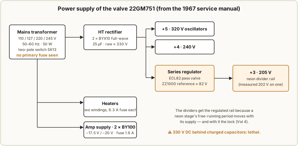
The 22GM751 service manual draws the power supply in full (manual, p. 22):
Table 1 — ([manual](https://www.sm5cbw.se/audio/philips/GM751.pdf), p. 22)
| Rail | Voltage | Feeds |
|---|---|---|
| Raw HT | about 330 V | from 2 × BYX10 silicon rectifiers, full-wave, 25 µF reservoir |
| +5 | 320 V | the master oscillators (an oscillator anode is marked 245 V after its load) |
| +4 | 240 V | — |
| +3 | 205 V, regulated | the neon dividers, through an ECL82 series regulator referenced to a ZZ1000 (about 82 V) |
| −1 / −2 | 17.5 V / 20 V | the transistor power amplifier, from 2 × BY100 |
| Heaters | 6.3 V | two windings, each with a 6.3 A fuse |
One owner measured 299 V on +5 and 202 V on +3 on a working 22GM751/00 (Circuits Online 116294). The AG7500 uses an EZ80 valve rectifier instead of the silicon diodes.
5.2 Safety specifics
It has a real mains transformer. The schematic shows a transformer with a tapped primary for 110, 127, 220 and 245 V at 50–60 Hz, 50 W, and an on/off switch (SK13) that breaks both poles. It is not a live-chassis AC/DC set. No source says whether the chassis is earthed or whether the original cord is two- or three-core; check the organ in front of you.
Look for a mains fuse. The parts list gives one 1.6 A fuse, on the amplifier’s low-voltage winding, and two 6.3 A fuses, on the heater windings. No fuse could be seen in the mains primary or the HT winding on the scanned schematic. If the organ really has none, fitting a correctly rated primary fuse is the first safety improvement to make.
Set the voltage selector. The selector covers 110 and 127 V as well as 220 and 245 V, so an organ can be set for North American mains; the AG7600 amplifier takes 90–245 V in eight steps (radiomuseum). One US dealer ran a European organ through a 2:1 step-down transformer before changing the selector (Chicago Electric Piano).
What restorers did. Replaced the mains cord and fuse (Circuits Online 148173); declined to replace a blown fuse without finding why it blew, since “fuses don’t blow for no reason” (Circuits Online 78678); disconnected and discharged the organ before probing (GroupDIY).
General valve practice. Bringing an unknown valve set up slowly on a variac, working through an isolation transformer, and fitting modern safety-rated capacitors on the mains side are standard practice for any equipment of this age. No Philicorda-specific source recommends them; they are not specific to this organ, but nothing about it makes them less sensible.
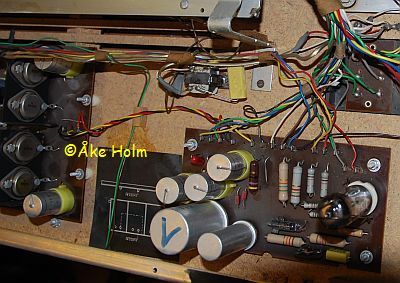
The divider boards sit at up to 205 V, and the trimmers that set them are on those boards. Adjust them only with an insulated trimming tool.
5.3 Buying one: what to check
Valve or transistor. On a GM751, look for a T at the end of the type number on the model plate: in every example found it marks the transistor version (Vol 1). With the back off, a neon organ shows ECC83 valves and rows of small glass tubes on its tone boards.
Before buying, from the faults owners actually report:
- Play every key on 8′, 4′ and 2′ separately. A dead or wrong note in one footage only points to a contact; the same fault in every key that uses one octave of one note points to a divider.
- Try the chord section (the lowest 17 keys, with the bass/chord switch in its third position), the vibrato and the reverb.
- Check the key plastics. They become brittle; one owner snapped a part during removal and published a tutorial on doing it safely (Liquitone, AG7500). The AG7500 and GM751 share the key mechanism, so parts can come from a donor.
- Note the voltage selector setting, and whether the knobs and swell pedal are present.
- On a neon organ, look for any flickering divider tube with the organ running.
Prices are too scattered to generalise. Data points found: a GM751 sold at auction in the Netherlands for €101 around 2021; a serviced transistor GM751 offered by a UK dealer at £695 before VAT; a Dutch forum estimate from 2009 of “€100+ working, €50 defective”; and a US classified asking $1,251 for a GM753. Several owners got their spare parts by buying a second organ.
5.4 Faults that owners have reported
These are first-hand accounts. Each is one case; none is a survey of how common the fault is.
Neon-divider organs
Table 2 — Neon-divider organs
| Model | Symptom | What was found | Source |
|---|---|---|---|
| 22GM751/00 | A note sounds noisy in some octaves; the matching ZA1001 flickers in the same rhythm | Owner replaced the tube and its 30 pF trimmer with no change; rails measured 299 V and 202 V. Suggestions: the 1 MΩ and 2.2 MΩ resistors, leaky capacitors, the BA100 (a 1N4148 was suggested as a substitute), ambient light. Unresolved. | Circuits Online 116294 |
| GM751 (rebuilt from two organs) | G♯ notes sounding as E or B; one note “droning, dissonant” | No cause recorded | GroupDIY 16139 |
| GM751 (valve) | ECC83 heaters dark | A good 6.3 A heater fuse making poor contact in its holder, and a defective headphone switch (which mutes the speakers) | GroupDIY 12376 |
| AG7500 | Broken key part | Brittle plastic; the key mechanism is shared with the GM751 | Liquitone |
The flicker-in-rhythm symptom is the loss of lock described in Vol 4, and the list of suspects matches that volume’s table: anything that moves a stage’s period can take it out of its lock range. Replacing the tube and trimmer did not cure it, which points at the resistors, the capacitors or the rail.
Transistor organs, for comparison
Table 3 — Faults that owners have reported
| Model | Symptom | What was found | Source |
|---|---|---|---|
| GM752 | One note gives only noise in every octave | The master oscillator’s tank and feedback capacitors had failed; replaced with polyester film, then retuned with the coil | Circuits Online 154066 |
| GM751 T | Several dead notes | Failed BF195 transistors | Circuits Online 87746 |
| GM751 T | Uneven 8′ on two notes after a recap | Cold joints on the board under the keys | Circuits Online 148173 |
| ”Fully transistorised” | No sound | A failed AC132 germanium output transistor | GroupDIY 32936 |
On the transistor organs a dead oscillator silences one note in every octave, because every octave is divided from it — the same logic as the neon organs.
Not found: first-hand Philicorda accounts of hum, scratchy tabs, specific electrolytic failures, wax or paper capacitors, or felt replacement. Those are reasonable things to check in any organ of this age, but there is no published Philicorda case to point to. On the 22GM751 the HT rectifiers are silicon, so a failed rectifier valve is a fault of the AG7500 (EZ80) only.
5.5 Finding ZA1001s
The ZA1001 has been out of production for decades. No price for one was found anywhere. New old stock appears occasionally — one seller offered six brown-dot tubes in the Dutch repair thread — but an owner on The Organ Forum in 2016 could not find any for sale and gave up. In practice, donor organs are where spare tubes come from: two independent forum threads describe cannibalising a second Philicorda (GroupDIY 16139, Circuits Online 70321).
Substitutes have been discussed but not, as far as could be found, built and reported:
- Other neons. A stage’s free-running period depends on its tube’s striking and extinction voltages (Vol 3), so a different tube moves the stage within its lock range, and the 30 pF trimmer has to absorb the difference. Common indicator neons have a narrower striking-to-extinction gap and are sensitive to darkness — the NE-2 family’s “dark effect” — which makes them a poor fit for a stage that must strike consistently inside a closed cabinet. The Neon Ring Counters dive, Vols 2 and 3, covers both problems. No report was found of an NE-2 or similar working in a Philicorda.
- Solid-state stages. Suggestions on The Organ Forum included a unijunction-transistor oscillator in place of the neon, and rebuilding the dividers from CD4013 flip-flops with a capacitor to restore a sawtooth. Neither is reported as completed.
- A replacement tone generator. Transplanting a top-octave-synthesiser board from another organ was also suggested. That would replace the instrument’s tone generation rather than repair it.
No commercial replacement divider board or retrofit kit was found, in English, Dutch or German.
5.6 The Philips tuning procedure
The service manual’s tuning instructions (Stimmvorschrift, p. 6) give three methods. In each, only the twelve master oscillators are adjusted, by turning the core of each oscillator’s coil; the dividers follow. The manual refers to a separate Philicorda Instruktionsbuch (code 93 752 91.1) for the full procedure; that book was not found online.
1. Against a reference generator. The manual specifies a Wandel & Goltermann STG-1 tuning-fork generator set to 440 Hz. Set the organ with one footage tab on, the bass/chord switch and SK12 in position 1, and vibrato off. Tune each note from a¹ to a² against the same note on the generator, by ear to zero beats, or with an oscilloscope: the organ’s signal (taken at the anode of valve B502b) on the vertical input, the generator on the horizontal, and the core turned until the Lissajous figure stands still. Any accurate modern tone source does the same job.
2. With a pitch pipe. A twelve-note chromatic pitch pipe, with vibrato and reverb off and a voice and footage chosen to match the pipe’s tone and octave. Blow each note, play it, and turn the core until the beats stop.
3. By beats. With vibrato and reverb off, start from a¹. Play it with the next note in the sequence, set that note’s core so the pair is pure, then turn the core down until the tabulated number of beats is heard; then move on to the next pair. The manual calls this the circle of fifths; worked within one octave it alternates fourths and fifths:
Table 4 — alternates fourths and fifths
| Pair | a¹–e¹ | e¹–h¹ | h¹–fis¹ | fis¹–cis¹ | cis¹–gis¹ | gis¹–dis¹ | dis¹–b¹ | b¹–f¹ | f¹–c¹ | c¹–g¹ | g¹–d¹ | d¹–a¹ |
|---|---|---|---|---|---|---|---|---|---|---|---|---|
| Beats per 10 s | 14 | 10 | 14 | 14 | 10 | 14 | 10 | 14 | 14 | 10 | 14 | 10 |
German note names: h is B, b is B♭, and the suffix -is is a sharp. One cell of the scanned table is faint. The manual uses two round figures throughout; in strict equal temperament the beat rate rises a little with pitch, so treat the table as a guide and check the result against a reference.
After any of the three, the manual adds one instruction: shifted dividers must be re-set.
5.7 Re-setting the dividers
This is the step with no published procedure. The service manual gives none, and the Dutch thread’s owner confirms that “for the shifted dividers you need other documentation” — presumably the missing Instruktionsbuch.
What follows is derived from how the stage works (Vol 3 and Vol 4), not taken from a Philips document:
- Let the organ warm up fully, and tune the masters first.
- Listen to, or put an oscilloscope on, one note’s chain at a time. A locked stage’s output is a steady sawtooth at exactly half the frequency of the stage above; on a dual-trace scope the two traces show a stable 2 : 1 pattern.
- For a stage that is unstable or at the wrong ratio, turn its 30 pF trimmer slowly with an insulated tool and note the two settings at which it drops out of ÷2. Set the trimmer midway between them.
- Move down the chain: each stage takes its kicks from the one above, so set the upper stages first.
- If a stage cannot be brought into lock at any trimmer setting, its period is outside the trimmer’s reach. Check the +3 rail (205 V) first, then the stage’s 2.2 MΩ resistor and timing capacitors, then the tube.
5.8 Documents and communities
Table 5 — Documents and communities
| Resource | What it has |
|---|---|
| 22GM751 service manual (German, 1967; also in this site’s Reference Library) | Block diagram, valve list, tuning procedure, all schematics. Hosted by Åke Holm, SM5CBW, with photographs. |
| radiomuseum: AG7500 and AG7600 | Eight and seven schematic sheets, available on request (not read for this dive) |
| drummachines.de: AG7500 | The best description of the AG7500’s circuits, in German |
| Circuits Online | The most technical repair threads, in Dutch |
| GroupDIY | Several GM751 and GM760 threads |
| philicorda.nl | A collector, René Eijsink, and the Viva Philicorda! festival in Zwolle; no repair service listed |
| SMEM | The Swiss museum’s AG7500 and GM752 entries |
The Organ Forum has threads on replacing ZA1001s and on troubleshooting a 751, but its pages refused automated reading and were not consulted directly. A 2026 restoration video by Emma Repairs, featured by Hackaday, shows the neon dividers of a working organ; what it found inside was not reviewed for this dive.
Comments (0)