Philips Philicorda · Volume 4
Pitch, Lock and Drift
Why a locked neon divider adds no pitch error, what makes it lose lock, and what each failure sounds like
A Philicorda’s tuning lives in twelve coil cores. Every pitch the organ can play is one of the twelve master oscillators divided by a power of two, so if the masters are in tune and every neon stage is locked, the whole keyboard is in tune — the dividers contribute no pitch error of their own. The catch is the word locked. A neon stage divides by two only while its own free-running period sits inside a band just above two periods of its input, and everything that ages in a sixty-year-old organ — the supply, the resistors, the capacitors, the tubes — pushes that period around. This volume separates the two questions a restorer has to keep apart: where the pitch comes from, and what makes a divider stop dividing by two.
4.1 Where the pitch comes from
The pitch of every note is set by its Hartley master oscillator, an LC circuit tuned by the slug in its coil (Vol 2). A neon stage that is locked fires once for every two firings of the stage above, so its frequency is exactly half of its input. It cannot run slightly sharp or slightly flat while it stays locked, because it is fired by the stage above rather than by its own timing.
Two things follow:
- Every octave of a note follows its master. If the G master drifts by a few cents as the organ warms up, all six G’s drift together and stay perfect octaves of one another. The keyboard can go out of tune between notes — G against D, say — but never between the octaves of one note while its dividers are locked.
- Vibrato reaches every octave. The vibrato frequency-modulates the twelve masters at 5–6 Hz (Vol 2), and every locked divider below passes the modulation down unchanged.
This is why the Philips tuning procedure (Vol 5) adjusts only the twelve coil cores, and why the service manual then adds one sentence about the dividers: after the masters have been adjusted, “shifted dividers must be re-set” (22GM751 service manual, p. 6).
4.2 Lock ranges
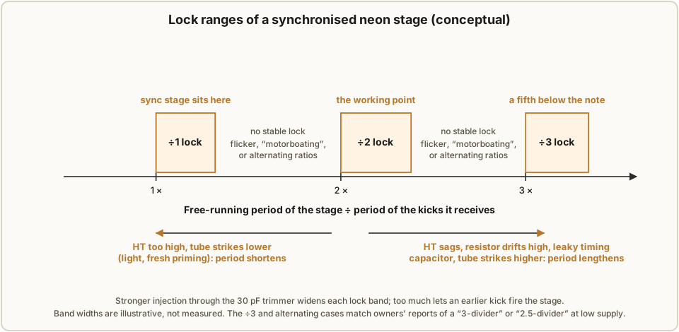
A synchronised relaxation oscillator does not divide by two under all conditions. Vol 3 described the mechanism: each stage is set to run, unaided, a little slower than half its input rate, and the second kick after each firing fires it early. That works only within a range.
- If the stage’s own period is too short — close to one input period — the first kick after a firing can already fire it, and it locks at ÷1 or flips between ratios.
- If it is too long — approaching three input periods — the second kick no longer finds the capacitor close enough to striking, and it waits for the third: the stage locks at ÷3.
- Between the lock ranges there is no stable ratio. The stage fires sometimes on one kick and sometimes on another, or free-runs between kicks.
The size of the kick, set by each stage’s 30 pF trimmer, sets the width of each range. A bigger kick lets the stage lock over a wider range of its own period, but too big a kick can fire it on the first kick instead of the second. Setting the trimmer is setting the stage’s position within its ÷2 range.
4.3 What moves a stage’s period
A stage’s free-running period depends on its resistor, its capacitors, its supply and its tube (the formula is in Vol 3). Each of them changes with age or conditions.
Table 1 — What moves a stage's period
| Cause | Effect on the period | Notes |
|---|---|---|
| Divider supply sags | longer | The capacitor charges more slowly towards a lower rail. The +3 rail is regulated by an ECL82 against a ZZ1000 reference for exactly this reason (Vol 5); a tired regulator valve or reference undoes it. |
| 2.2 MΩ resistor drifts up | longer | Old high-value carbon resistors commonly drift upward; the ageing of the 2.2 MΩ and 1 MΩ resistors is named as a known fault in the Dutch repair thread (Circuits Online 116294). |
| Timing capacitor leaks | longer | Leakage diverts some of the charging current. The yellow polyester capacitors used throughout are suspected by repairers of intermittent leakage that shows mainly at high voltage, where an ohmmeter will miss it (Circuits Online 154066). |
| Tube strikes higher | longer | Owners report that neon striking voltage creeps up with age; loss of priming makes striking later and less consistent. |
| Tube strikes lower | shorter | Light lowers a neon’s striking voltage; a forum contributor suggests UV or fluorescent light as a test of a doubtful stage. |
| Supply too high | shorter | A rail set or drifting high charges every stage faster. |
Most of the ageing in the table pushes the same way — towards a longer period, towards the ÷3 edge. That fits the reports from owners. A Dutch contributor notes that with too low a supply “you sometimes get a 2.5-, 2- or 3-divider” (Circuits Online 116294) — a stage locking at ÷3, or alternating between ÷2 and ÷3.
4.4 What each failure sounds like
Because the neon stages are oscillators rather than counters, a failing stage does more than drop a note or an octave. The table derives the sound of each case from the circuit; the first row is the one case reported first-hand.
Table 2 — What each failure sounds like
| What the stage does | What you hear | Where |
|---|---|---|
| Loses lock: fires on irregular kicks or free-runs between them | A rough, noisy or “motorboating” tone; the stage’s neon visibly flickers in the same rhythm. Reported on a 22GM751/00 (Circuits Online 116294). | That octave of that note; the stages below are fed an irregular input |
| Locks at ÷3 | The stage’s output is two-thirds of the correct frequency: a perfect fifth below the note it should play | That octave of that note; the stages below receive an input they were not set up for and may lock wrongly too |
| Alternates ÷2 and ÷3 (the “2.5-divider”) | An irregular waveform with strong sub-harmonics: a growl under the note | As above |
| Stops striking | That octave of that note goes silent | The stage below loses its kicks and free-runs at its own period, slightly flat and drifting, unrelated to the note |
| Locks at ÷1 | The stage repeats the octave above | That octave sounds an octave high |
The last three rows are derived from how the circuit works, not from reports. One owner’s account of notes sounding as quite different notes — G♯ keys sounding as E or B on a GM751 rebuilt from two organs (GroupDIY) — does not match any single divider failure in the table, and the thread does not record a cause.
One consequence is worth stating plainly. The claim, made in the sibling Neon Ring Counters dive before it was corrected, that a neon divider “never detunes” is true only while the stage is locked. A stage that has lost lock can produce a pitch unrelated to the note: a fifth below, a growl, or a free-running tone a little flat of where it should be.
4.5 Why the dividers must be re-set after tuning
The manual’s instruction to re-set shifted dividers after tuning makes sense in these terms. Turning a coil core changes the master’s frequency, and with it the input period of every stage in that note’s chain. A stage sitting near the edge of its ÷2 range before tuning can be left outside it afterwards. Re-setting a divider means turning its 30 pF trimmer until the stage is back in the middle of its range. The manual gives no procedure for this; Vol 5 sets out what is known.
4.6 Counting dividers and synchronised dividers
The transistor Philicordas divide with flip-flops (Vol 2), which change state on every input edge and therefore divide by exactly two regardless of component values, until something actually fails. In that sense they are more robust than the neon stages: they have no lock range to drift out of.
The neon design has its own engineering logic. Each octave costs one tube, one resistor, two capacitors, one diode and one trimmer, all running from a single regulated rail. And the output of each stage is already a sawtooth, which contains every harmonic of the note and gives the Vox filters plenty to work on. A flip-flop’s natural output is a square wave, which contains only odd harmonics. Philips’s own reasons for choosing neon dividers are not recorded in anything found for this dive.
4.7 “Consistent over the years”
The English Wikipedia article says that the Philicorda’s “typical warm tone, originally produced using neon bulb based octave dividers, was consistent over the years”. The first half is supported: the early organs’ tone did come from neon dividers. The second half is the article’s own uncited judgement, and it is disputed by the article itself, which says the sound “differed slightly” between models, and by a Sound On Sound review that describes audible differences between the GM751/752 and the GM754 (Sound On Sound). The neon and transistor organs produce their tones in different ways — sawtooths from relaxation oscillators against the outputs of flip-flops — so some difference is to be expected; how large it is, and how much of it survives the Vox filters, is a question for ears and recordings rather than for this volume (Vol 6).
Comments (0)