Philips Philicorda · Volume 2
Tone Generation — Twelve Oscillators and Seventy-Three Neons
The master oscillators, the divider chains, the keying, the voices and the amplifiers of a neon-divider Philicorda
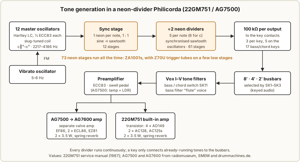
A neon-divider Philicorda makes every one of its pitches from just twelve valve oscillators. Each oscillator produces one note of the top octave as a sine wave; a neon stage turns that sine into a sawtooth at the same frequency; and five more neon stages below it each produce the same note an octave lower than the stage above. All seventy-three neon stages run the whole time the organ is switched on, and the keys do nothing more than connect already-running tones to a few busbars on their way to the filters and the amplifier. This volume follows a note from oscillator to loudspeaker, using the 1967 service manual for the valve 22GM751 as the primary source and noting where the earlier AG7500 is known to match.
2.1 The master oscillators
The manual’s description of the block diagram puts it plainly: the twelve highest notes, from c⁵ at 4186 Hz down to c♯⁴ at 2216 Hz, are generated by twelve master oscillators, each of which produces a sine wave (22GM751 service manual, p. 4). The note names are Helmholtz notation, in which c¹ is middle C; in scientific pitch notation the top octave runs from C♯7 to C8.
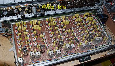
Each oscillator is one half of an ECC83 double triode in a Hartley circuit: an LC tank of a tapped coil and a 5.1 nF capacitor, with the coil’s tap to ground and feedback to the grid through 3.3 nF. The triode’s anode load is 47 kΩ from the +5 supply rail, and the anode is marked 245 V on the schematic. The six ECC83s on the three oscillator-and-divider boards (Units J, K and L) therefore carry all twelve oscillators. The output is taken through a 10 nF capacitor and a 4.7 kΩ resistor to the first neon stage.
Each oscillator is tuned by its coil core, an adjustable slug inside an aluminium can; the tuning procedure in Vol 5 consists of nothing else. A German enthusiast’s description of the AG7500 gives the same arrangement — two generator boards of six oscillators, each on half an ECC83, tuned by the movable coil core (drummachines.de, AG7500) — and a second German site also counts twelve oscillators with ECC83s (wernbo.de). SMEM’s figure of “10 oscillators” for the AG7500 is very likely a garbled count of its ten conventional valves.
Vibrato is applied at the source. On the GM751 a separate oscillator, switched in by the vibrato tab, varies the master oscillators’ frequency at 5–6 Hz through a 100 kΩ resistor into each oscillator’s grid circuit (manual, p. 4 and the Unit J schematic). Because every lower octave is derived from its master, the vibrato reaches every octave of every note together. On the AG7500 the vibrato is described as fixed at 6 Hz with no depth control (drummachines.de); the Dutch Wikipedia says the rate is fixed and the depth adjustable — one of several small disagreements between the secondary sources.
2.2 Seventy-three neon stages
Each master oscillator feeds a chain of neon stages (Vol 3 has the circuit):
- The first stage — the sync stage — runs at the oscillator’s own frequency and converts the sine wave into a sawtooth. There is one per note: 12 in all.
- Each following stage runs at half the frequency of the one above it. Every note is divided five times, except c, which is divided six times: 11 × 5 + 6 = 61 dividing stages.
That gives 12 + 61 = 73 neon stages, and the parts lists agree exactly. The GM751 manual lists 68 × ZA1001 and 5 × Z70U — 73 tubes — together with 61 × BA100 diodes, one for each dividing stage. The AG7500 has the same total with a different split, 70 × ZA1001 and 3 × Z70U, according to both radiomuseum and SMEM. The Z70U is a three-electrode trigger tube, used on a few of the lowest-pitched stages (Vol 3).
The 73 stages produce 73 different pitches: six octaves of each of the twelve notes, from c♯ to c⁵, plus the extra low C. That runs from C at 65.4 Hz (c⁵ ÷ 64) up to c⁵ at 4186 Hz, matching the 65–4186 Hz range in the manual’s specification. On the usual organ convention, in which 8′ low C is 65.4 Hz, that is also exactly the 49 notes of the keyboard at 8′ pitch — low C at 65.4 Hz up to c³ at 1046.5 Hz — plus the two extra octaves that the 4′ and 2′ footages need at the top of the keyboard.
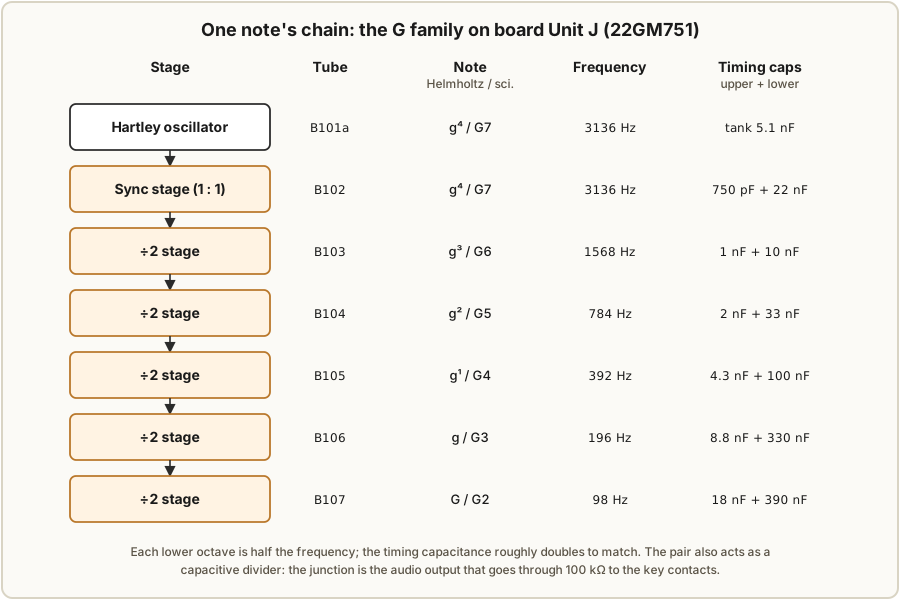
The table gives the G chain in full, from the Unit J schematic. The timing capacitance roughly doubles from one stage to the next, as it must for a relaxation oscillator running at half the frequency; Vol 3 explains the pair of capacitors and checks the values.
Table 1 — Seventy-three neon stages
| Stage | Tube | Note | Frequency | Timing capacitors (upper + lower) |
|---|---|---|---|---|
| Oscillator | ½ ECC83 (B101a) | g⁴ (G7) | 3136 Hz | tank 5.1 nF |
| Sync | B102 | g⁴ (G7) | 3136 Hz | 750 pF + 22 nF |
| ÷2 | B103 | g³ (G6) | 1568 Hz | 1 nF + 10 nF |
| ÷2 | B104 | g² (G5) | 784 Hz | 2 nF + 33 nF |
| ÷2 | B105 | g¹ (G4) | 392 Hz | 4.3 nF + 100 nF |
| ÷2 | B106 | g (G3) | 196 Hz | 8.8 nF + 330 nF |
| ÷2 | B107 | G (G2) | 98 Hz | 18 nF + 390 nF |
2.3 Keying: the keys switch audio, not oscillators
Every divider runs continuously, so pressing a key cannot start a tone; it only routes tones that already exist. Each divider output passes through a 100 kΩ resistor to the key contacts (manual, p. 4). Each key has three contacts, one for each footage, and the 17 lowest keys, which double as bass and chord keys, have five. At rest a contact is grounded; pressed, it connects its tone to a busbar for 8′, 4′ or 2′, and the footage tabs (SK1 to SK3) decide which busbars reach the rest of the organ. The AG7500 description agrees: three contacts per treble key, more in the bass (drummachines.de). This is keyed audio, the usual arrangement for divider organs of the period, and it has one practical consequence for a restorer: a dirty contact affects one footage of one key, while a faulty divider affects one note in every key that uses it (Vol 5).
2.4 Voices, bass and chords
From the busbars the signal goes through five tone filters, Vox I to V, switched by rocker tabs (SK4 to SK8). The divider output is a sawtooth, rich in harmonics, so the filters work by taking harmonics away — the subtractive approach of most divider organs. The manual does not describe the filters in detail beyond the schematic, and this dive does not attempt to characterise each voice.
A three-position switch, SK11, sets the lower part of the keyboard. In its first position the keyboard plays normally. In the second, keys 1 to 17 become a bass section at 4′ + 2′ through a special filter the manual describes as having a flute character. In the third, the lowest keys play one-finger chords using their extra contacts. The split is between keys 17 and 18 (manual, p. 4; SMEM and wernbo.de agree). One owner notes that the 17 preset chords include no E chord (combo-organ.com).
2.5 Expression and the amplifiers
The swell pedal of the AG7500 is optical: a lamp fed with 6.3 V shines on a light-dependent resistor through a shutter moved by the pedal (drummachines.de). The two ECC83s not used as oscillators serve as the preamplifier and vibrato oscillator on the GM751 (“Vorverstärker + Vibrato-Oszillator: 2x ECC83”, manual, p. 2).
The power stages differ by model:
Table 2 — The power stages differ by model
| AG7500 | 22GM751 (valve) | |
|---|---|---|
| Power amplifier | separate AG7600: EF86, 2 × ECL86, EZ81 rectifier, 2 × 3.5 W, spring reverb | built in, transistor: 4 × AD149, 2 × AC128, 3 × AC125; 2 × 3.5 W, spring reverb |
| Speakers | 2 × elliptical AD3570AM in the AG7600 | 2 × AD3701RM, 400 Ω |
| HT rectifier | EZ80 valve | 2 × BYX10 silicon |
| Divider supply | ECL82 and ZZ1000 present; role not documented for this model | regulated by an ECL82 against a ZZ1000 reference (Vol 5) |
The AG7600 figures are from radiomuseum; the GM751 figures are from the service manual. The GM751’s two BY100 diodes rectify the low-voltage supply for the transistor amplifier.
2.6 Valve complement
Table 3 — Valve complement
| AG7500 | 22GM751 (valve) | |
|---|---|---|
| ECC83 | 8 | 8: 6 as oscillators, 2 as preamplifier and vibrato |
| ECL82 | 1 | 1, divider-rail regulator |
| EZ80 | 1 | — |
| ZZ1000 | 1 | 1, voltage reference |
| Z70U | 3 | 5 |
| ZA1001 | 70 | 68 |
| BA100 diodes | not documented | 61 |
On the AG7500 the split of the eight ECC83s is not documented; by analogy with the GM751 it is very probably six oscillators and two preamplifier and vibrato stages, and the ECL82 very probably regulates the divider rail, but the AG7500 schematics would be needed to confirm either.
2.7 How the transistor generation differs
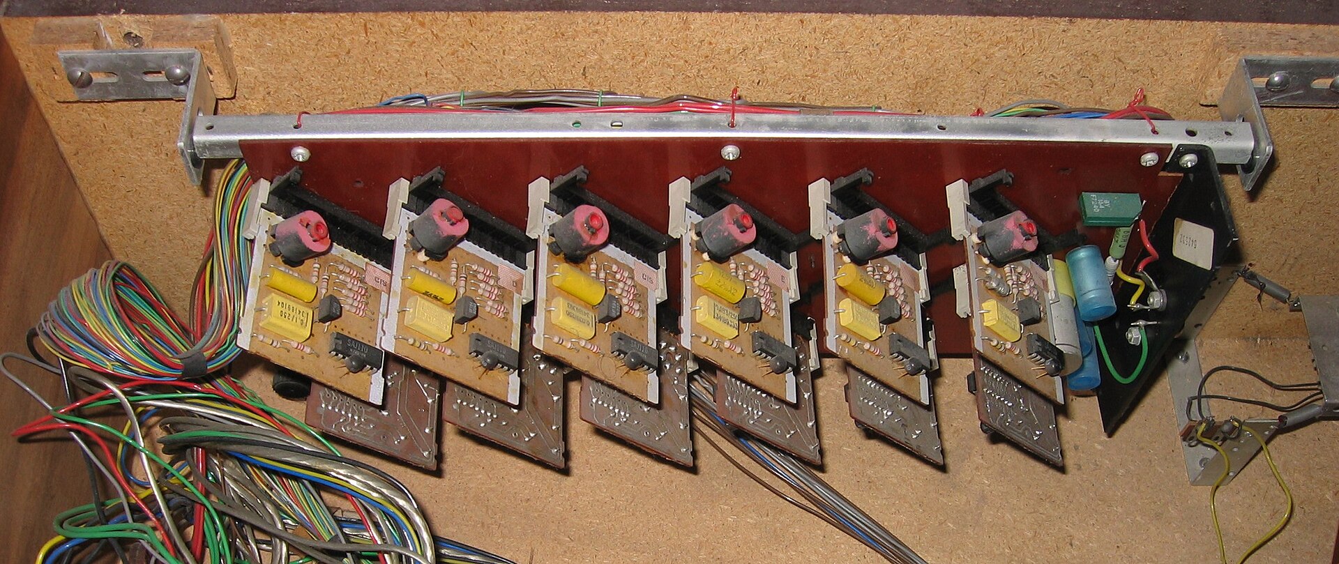
The transistor Philicordas keep the twelve-oscillator idea and replace almost everything else. On the GM752 each master oscillator is still a Hartley LC circuit tuned by its coil, now built around a BF194 transistor (Circuits Online 154066). The dividers become flip-flops — at first discrete two-transistor circuits and later the Philips SAJ110 IC (German Wikipedia) — which count input cycles and so divide by exactly two every time. On the GM760 each note’s oscillator and divider chain sits on its own small board.
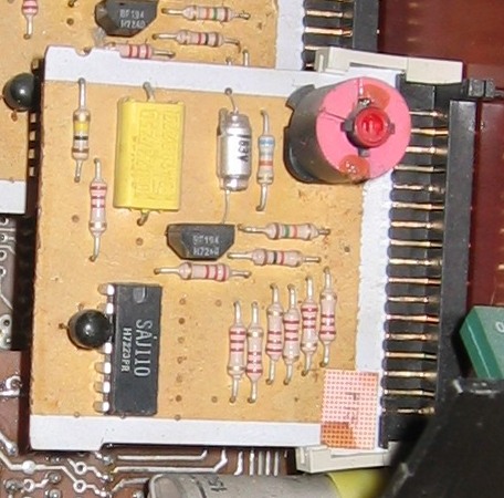
The voice changed with it. A flip-flop’s natural output is a square wave, not a sawtooth, and owners and reviewers note audible differences between models (Vol 6). For the rest of this dive, Philicorda means the neon-divider instruments unless a transistor model is named.
Comments (0)