Philips Philicorda · Volume 1
The Philicorda — Philips's Neon-Divider Organ
What the Philicorda is, where it came from, the whole model family, and which versions really divide their octaves with neon tubes
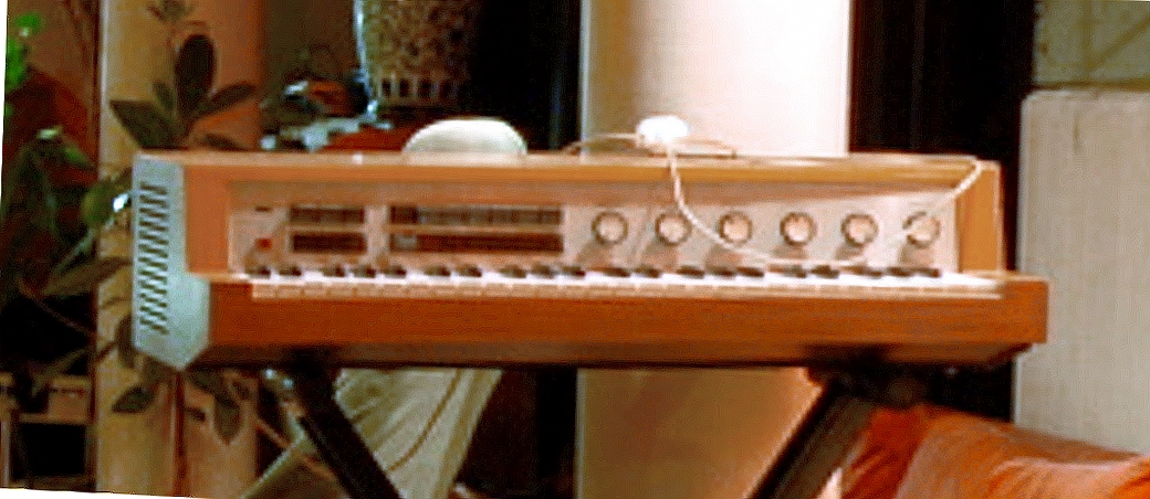
The Philips Philicorda is a small, single-keyboard home organ from the Netherlands that looks, from the front, like nothing more exotic than a wooden box with a row of rocker tabs and six chrome knobs. Open the lid of one of the early ones, though, and there is a sight no other organ of its era offers: rows of little glass neon tubes, seventy-odd of them, standing among yellow capacitors on the tone boards. Each of those tubes is a tiny oscillator, and together they turn twelve valve oscillators into every note on the keyboard by repeatedly halving their frequency. The transistor was already taking over electronic music when the first Philicorda went on sale in 1963, and Philips built its tone generator from valves and gas tubes anyway. This six-volume dive explains how that generator works, why it is better described as a chain of synchronised oscillators than as a counter, how it keeps — and loses — its pitch, and what it takes to keep one running sixty years later.
1.1 What the Philicorda is
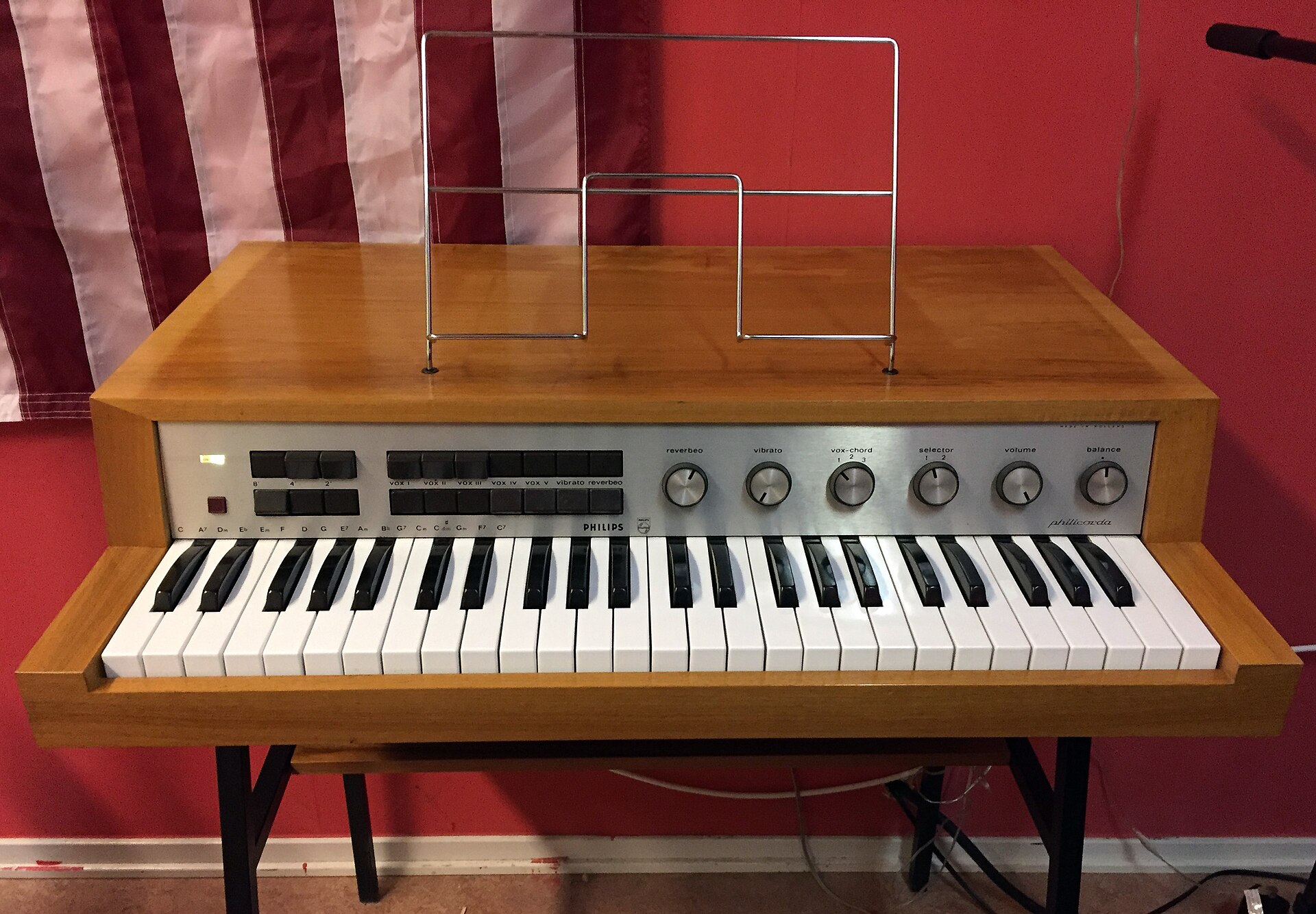
The Philicorda is a 49-key, single-manual electronic organ — four octaves, starting on C — built by Philips in Eindhoven for the home market, and the company’s first musical instrument. Its controls are the same across the early models: three footage tabs (8′, 4′ and 2′) that choose which octaves of each note sound, five voice tabs labelled Vox I to V that switch tone-shaping filters, a bass-and-chord switch that turns the lowest 17 keys into a bass section with one-finger chords, vibrato, and a swell pedal. From 1965 the organ carried its own amplifier, speakers and spring reverb; the first production model, the AG7500, sat on a separate valve amplifier, the AG7600.
What makes it interesting to an electronics reader is the inside. Every electronic organ of the period had to solve the same problem — producing sixty-odd stable pitches without building sixty-odd oscillators — and the usual answer was octave division: build one oscillator for each of the twelve notes in the top octave, then halve each one’s frequency repeatedly to get the same note in every octave below. The early Philicordas did the halving with neon switching tubes, Philips type ZA1001, wired as relaxation oscillators that lock to the stage above at half its rate. That is the same glow-discharge physics the sibling Neon Ring Counters dive covers in depth, applied at audio frequencies in a mass-produced instrument.
1.2 Where it came from
The Philicorda came out of the Philips physics laboratory in Eindhoven, the NatLab, where the composers Tom Dissevelt and Dick Raaijmakers worked on electronic music in the early 1960s. All three of the English, Dutch and German Wikipedia articles make that connection and say the first instrument, the AG7400 of 1961, was developed there (English, Dutch, German); no primary Philips source for it was found, and no individual circuit or industrial designer is named anywhere. The Dutch and German articles, and the Swiss museum SMEM, call the AG7400 a prototype; the English article says it was launched onto the market. The safer reading is that 1961 was the prototype year and that the organ was launched under the name Philicorda as the AG7500 at the beginning of 1963 (SMEM, AG7500).
Production ran until 1979, through two generations of electronics and a long line of model numbers. The Dutch and German Wikipedia articles say that Philips took more than 60 % of the home-organ market with it; neither cites a source, so treat that figure as a claim. In the United States the department-store chain J. C. Penney sold the portable GM753 under its own Penncrest name, at about $1,250 new (combo-organ.com). The original guilder price, and what the name Philicorda was meant to suggest, were not found in any source.
1.3 The model family
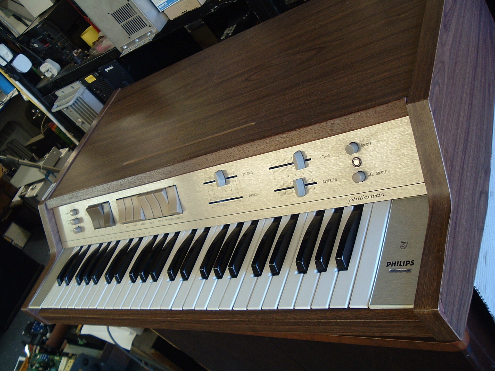
Model numbers changed from an AG prefix (the AG7400 and AG7500) to GM numbers from the mid-1960s, usually written with a 22 in front — 22GM751, 22GM753 — and a market suffix after a slash: /00, /15, /22 and so on. The 22GM751 service manual covers suffixes /00 to /50 under the same 22GM751 heading, so the leading 22 is part of the Philips product code for every market, not, as one dealer article says, a mark of a German export.
Table 1 — The model family
| Model | Year | Keyboard | Tone generator | Neon dividers? |
|---|---|---|---|---|
| AG7400 | 1961 | 1 × 49 keys | not documented | not documented |
| AG7500 | early 1963 | 1 × 49 keys | 12 valve oscillators; 70 × ZA1001 + 3 × Z70U | yes |
| AG7600 | c. 1963 | — | the AG7500’s separate valve amplifier and speakers | n/a |
| ”750 series” | 1965 | 1 × 49 keys | built-in amplifier, reverb; dividers not documented | not documented |
| 22GM751 (no T suffix) | c. 1965–67 | 1 × 49 keys | 12 valve oscillators; 68 × ZA1001 + 5 × Z70U; transistor power amplifier | yes |
| GM751 with T suffix | c. 1967 on | 1 × 49 keys | all transistor | no |
| GM752 | late 1967 | 1 × 49 keys | transistor oscillators (BF194) | no |
| GM753 (Penncrest) | late 1967 | 1 × 49 keys | portable, no built-in speakers; transistor | no (see below) |
| GM754 | early 1970s | 1 × 49 keys | all transistor; slider controls | no |
| GM760 · GM761 | 1970s | 2 manuals | 12 tone generators with SAJ110 flip-flop ICs; GM761 adds a cassette recorder | no |
| GM758 · GM762 (PhilicordaRhythm) | late 1970s | 2 manuals | rhythm unit; GM762 adds auto-accompaniment | no |
Sources for the table: the 22GM751 service manual (1967), radiomuseum and SMEM for the AG7500 and AG7600, the three Wikipedia articles for dates and the later models, and Dutch repair threads on Circuits Online for the GM751 variants (cited in Vols 2 and 5). The dates of the GM751 vary between sources — 1965, 1966–67 and 1967 all appear — and a “750 series” of 1965 in the Dutch and German articles is probably part of the same confusion.
1.4 Which ones use neon dividers
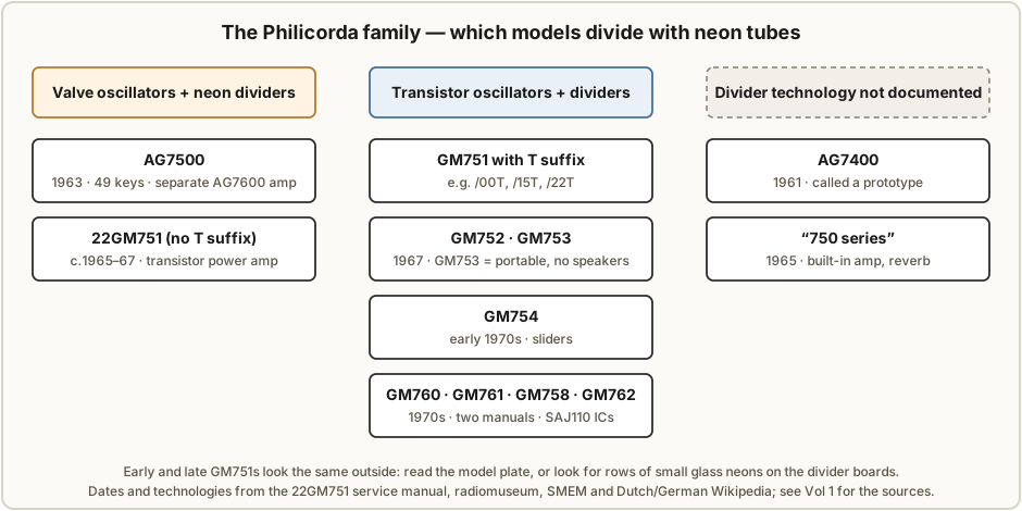
Only two models are documented with neon dividers: the AG7500 and the valve version of the 22GM751.
- The AG7500’s parts list — 8 × ECC83, 1 × ECL82, 1 × EZ80 rectifier, 1 × ZZ1000, 3 × Z70U and 70 × ZA1001 — is given by both the radiomuseum entry and SMEM.
- The 22GM751 service manual lists 68 × ZA1001 and 5 × Z70U on the divider boards, with six ECC83s as oscillators and a transistor power amplifier (manual, hosted by SM5CBW).
The change to transistors happened inside the GM751, not between model numbers. A Dutch repair thread distinguishes the valve 22GM751/00 from the all-transistor GM751/00T (Circuits Online 116294), and every T-suffix example found — /00T, /15T, /22T — is transistorised, including a serviced “13GM751 15T” sold by the UK dealer Soundgas and a Greek GM751 described as “fully transistorized, like the 752 model, no tubes-neon bulbs at all” (Circuits Online 148173). No source states the rule outright, but in every example found a T at the end of the type number means transistor.
Two gaps remain. Nothing found describes the dividers of the 1961 AG7400 prototype or of the 1965 “750 series”. And the GM753 is called fully transistorised by the English Wikipedia, while a US seller described a GM753 with “12AX7 tubes, Z70Us and a bunch of small triodes” — possibly an early GM753, possibly a mislabelled organ. Until a model plate settles it, this dive treats the GM753 as transistor.
1.5 Telling them apart
The cabinet will not tell you: early and late GM751s “look identical from the outside” (combo-organ.com). Two checks do.
- The model plate, on the underside: a T at the end of the GM751 type number means the transistor version.
- The inside: with the back or lid off, a neon-divider organ shows ECC83 valves and long rows of small glass neon tubes on its tone boards (photographs in Vol 2). A transistor organ shows small circuit boards with transistors and, on the 1970s models, ICs.
1.6 The AG7600 amplifier
The AG7500 is only a tone generator and preamplifier; it has no power stage. It played through the AG7600, a separate valve amplifier and speaker base with spring reverb: an EF86 (or E80F) preamplifier, two ECL86 output valves and an EZ81 rectifier, giving 2 × 3.5 W into two elliptical speakers, in a cabinet of 760 × 170 × 260 mm weighing 9.1 kg (radiomuseum, AG7600). SMEM and one German enthusiast page give the output valves as “ECC86”, which is a low-voltage double triode and not an output valve; ECL86, as radiomuseum and drummachines.de give it, is almost certainly right. From the 22GM751 on, the amplifier, speakers and reverb are built in, and on the GM751 the power amplifier is already transistorised even in the valve version.
1.7 How this dive is organised, and what it rests on
- Vol 2 — Tone generation. The twelve Hartley oscillators, the 73 neon stages, the keying, the voices and the amplifiers, with one note’s chain traced stage by stage.
- Vol 3 — The ZA1001 divider stage. What is and is not known about the tube, the stage circuit with its values, and how a pulse from the stage above makes it divide by two.
- Vol 4 — Pitch, lock and drift. Why the dividers add no pitch error while they are locked, what makes them lose lock, and what that sounds like.
- Vol 5 — Restoration. Safety, the faults owners have actually reported, ZA1001 supply, and the Philips tuning procedure.
- Vol 6 — Sound, players and plugins. The voice, who is documented as using one, and the software that models it.
The backbone is a primary document: the Philips service manual for the 22GM751, 22 pages in German dated 1967, which gives the block diagram, the valve list, the tuning procedure and full schematics of the oscillator and divider boards. It is held in this site’s Reference Library, and the original scan is hosted by Åke Holm, SM5CBW. The AG7500’s own schematics exist (radiomuseum lists eight sheets) but were not read for this dive, so where a GM751 fact is carried over to the AG7500 the text says so. Forum reports are used for faults and repairs, and each is cited where it is used.
One correction to the record belongs here. The sibling Neon Ring Counters dive describes the Philicorda’s divider stages as exact counting dividers that can drop an octave but never detune. The service manual describes them differently — as sawtooth oscillators that are synchronised to the stage above — and owners report stages locking at the wrong ratio when the supply is low. Vol 4 sets out what that means for the pitch; the Neon Ring Counters volumes have been corrected to match.
Comments (0)