Neon Ring Counters · Volume 8
High-Voltage Supplies — the Traditional Way
Mains transformer, valve rectifier, choke or capacitor filter, and a VR-tube shunt regulator — the cold-cathode-era HV supply, with worked schematics
A neon ring counter is only as steady as the rail that feeds it, and for the first thirty years of cold-cathode counting that rail was made entirely of parts you could see glowing in the dark: a mains transformer humming at the back of the chassis, a valve rectifier lit orange with its heater, an oil-filled reservoir capacitor the size of a soup tin, an iron choke, and — the clever bit — a slim glass tube of gas that did nothing but sit there and hold the voltage constant. That last part, the voltage-regulator (VR) tube, is a close cousin of the very neon lamps this whole series is about: it is a cold-cathode glow discharge running deliberately on the flat part of its V–I curve, where a large swing of current barely moves the voltage. This volume walks the traditional supply from the wall socket to the regulated rail, shows both filter styles with their ripple trade-offs, explains how a VR tube regulates and how to set its current, tabulates the classic tube types, shows how to stack them for higher rails, and finishes with a complete worked supply you could build for the reference ring counter of Vol 13. The modern boost-converter way — 5–12 V stepped up with a switching IC — is Vol 9; this is the old way, and it is still a lovely way to power a tube counter that deserves tubes all the way down.
⚠ Every rail in this volume sits between roughly 100 V and 450 V DC, behind a reservoir capacitor that stays charged long after you switch off. That is more than enough to kill you, and unlike mains it neither trips a breaker nor announces itself. Treat every node as lethal until a meter proves it discharged; the full safety discipline — bleeder resistors, the single-hand rule, discharge tools — is Vol 14, and it is not optional reading before you build any of this.
8.1 The shape of a classic HV supply
Strip a valve-era counter supply to its skeleton and it is always the same five blocks in a
row: a mains transformer to get the voltage into the right region and isolate you from
the line, a rectifier to turn AC into pulsating DC, a filter (choke and/or
capacitors) to smooth those pulses into something flat, a series resistor, and a VR
tube hanging from the output to ground that pins the rail to a fixed voltage. The first
four blocks make a raw DC rail that is roughly the right size but wobbles with the mains
and with load; the VR tube is what makes it stiff. As Vol 7 argued at length, a stiff,
regulated rail is the single highest-leverage thing you can do for a neon ring counter,
because every volt the supply drifts eats directly into the tiny Vs−Vm margin the lamps
depend on. The traditional supply earns its keep precisely there.
J. B. Dance’s Electronic Counting Circuits (1967) — the canonical reference for this whole dive — devotes much of its supply discussion to exactly this arrangement, because in its day there was no other. Every dekatron scaler, every trigger-tube register, every neon ring in a lab instrument sat on a rail built this way. The blocks below are worth understanding individually, because you will mix and match them: a selenium stack instead of a valve, a choke-input filter instead of capacitor-input, one VR tube or a stack of them.
8.2 From mains to raw DC: the transformer and rectifier
The transformer does two jobs at once. It isolates the counter from the mains — a non-negotiable safety requirement, never run a counter chassis from an autotransformer or a transformerless “line-derived” rail — and it sets the secondary voltage so that after rectification and filtering the raw DC lands comfortably above the VR tube’s striking voltage with headroom to spare. For a +150 V regulated rail we want raw DC in the region of 220–250 V, so a secondary of about 250-0-250 V RMS (centre-tapped, for full-wave rectification) or a single 250 V RMS winding into a bridge is the usual starting point. Size the secondary current rating for the total the supply will draw — the VR-tube current plus the load plus a comfortable margin; a 60–90 mA secondary is generous for a neon counter.
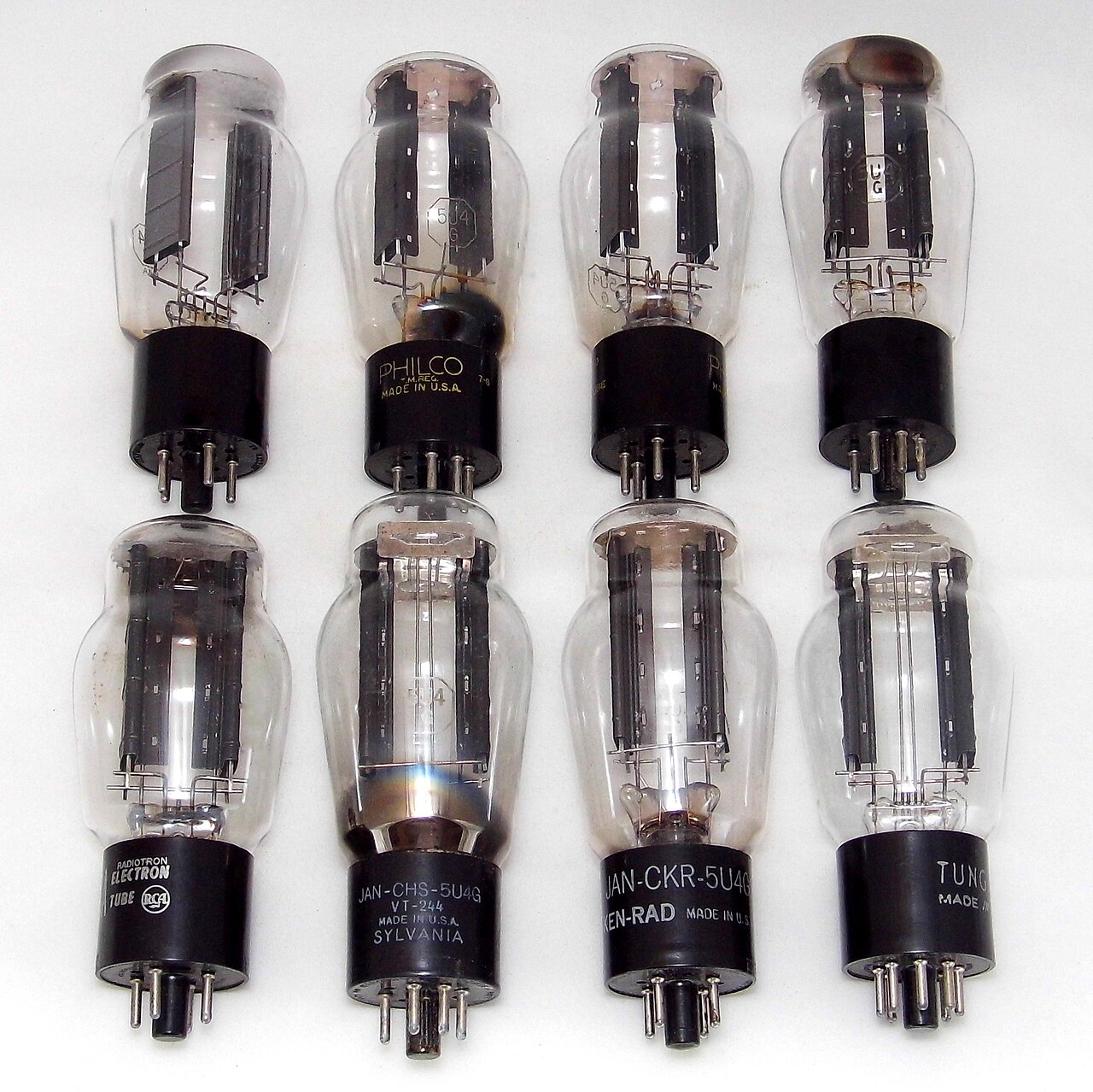
The rectifier turns that AC into pulsating DC. The traditional choice is a valve rectifier, and it comes in two flavours. A full-wave directly- or indirectly-heated rectifier — the miniature indirectly-heated EZ80 (6CA4), good for around 90 mA, or the big directly-heated octal 5U4 (GZ32-class), good for several hundred mA — has two anode plates and a single cathode, and with a centre-tapped secondary it rectifies both halves of the mains cycle. A valve rectifier’s forward drop is not negligible (tens of volts, and it rises with current), and its slow warm-up is actually a feature here: the HV rail comes up after the heaters, so the reservoir capacitor is not slammed with an inrush surge at the instant of switch-on. The alternative from the same era is a selenium rectifier stack — a column of selenium-coated plates, silent, instantly on, but with a larger and more temperature-dependent forward drop, a finite life (selenium ages and its drop creeps up), and the infamous smell when one fails. A modern builder will usually just substitute a string of 1N4007 silicon diodes (1000 V, 1 A each) for the rectifier and keep the rest of the supply period-correct; if you do, add a little series resistance or keep the transformer’s own winding resistance in mind, because silicon’s near-zero drop lets the reservoir charge to a higher peak than the old valves allowed.
8.3 Smoothing: capacitor-input versus choke-input
Rectified DC is not flat — it is a train of humps at twice the mains frequency (100 Hz from a 50 Hz line, 120 Hz from 60 Hz). The filter’s job is to fill in the valleys. There are two classic topologies and the choice genuinely matters for a VR-regulated supply.
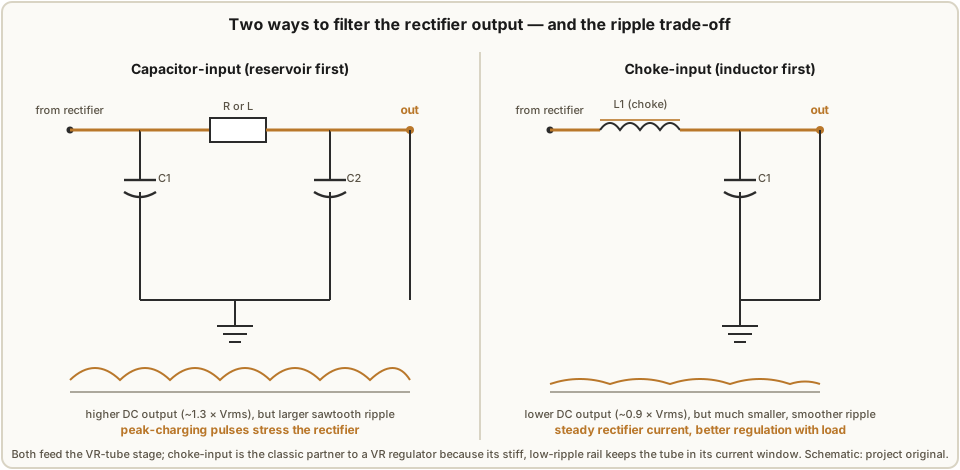
In a capacitor-input filter the reservoir capacitor comes first, straight off the
rectifier. It charges to near the peak of the secondary, so the DC output is high —
roughly 1.3 × the RMS secondary voltage at light load. The price is twofold: the ripple
is a relatively large sawtooth (the cap discharges into the load between humps), and the
rectifier only conducts in short, tall current spikes at each peak, which stresses the
valve and makes the output sag noticeably as load increases. You then follow the reservoir
with a series resistor or a choke and a second capacitor to knock the ripple down further.
For a capacitor-input filter the ripple falls as you increase the reservoir capacitance and
the load resistance; a useful rule of thumb for a full-wave supply is that the ripple factor
is approximately r ≈ 2.4 / (C · R_L) with C in µF and R_L in kΩ — so a 16 µF reservoir
into a 10 kΩ load gives roughly 1.5 % ripple before any second stage.
In a choke-input (or “swinging-choke”) filter the inductor comes first, then the
capacitor. The choke forces the rectifier to conduct continuously rather than in spikes,
which is gentler on the valve and — crucially — makes the output voltage far less sensitive
to load current. The DC output is lower, about 0.9 × the RMS secondary voltage, and the
ripple is much smaller and more sinusoidal. The full-wave choke-input ripple factor is
approximately r ≈ 0.83 / (L · C) with L in henries and C in µF (for a 60 Hz line;
about 1.2 / (L · C) for 50 Hz, since the ripple frequency is lower), so a 10 H choke and a 16 µF capacitor give roughly
0.83 / 160 ≈ 0.0052, about 0.5 % ripple — around 1 V RMS on a 230 V rail before the VR
tube even sees it. Choke-input needs a minimum load current to keep the choke in
continuous conduction (below it the output jumps up toward the capacitor-input value), but a
VR tube drawing 15–25 mA is itself that minimum load, which is one reason choke-input and VR
regulation are such natural partners. For a neon counter supply, choke-input is the
classic and better choice: its stiff, low-ripple raw rail keeps the VR tube comfortably
inside its current window across the whole load range.
8.4 How a VR tube regulates
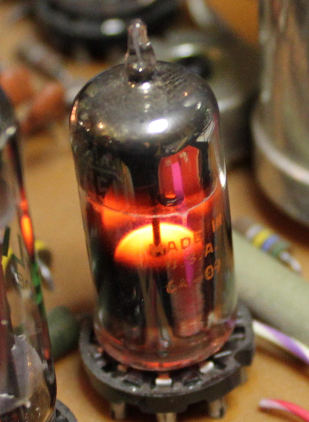
A voltage-regulator tube is a cold-cathode shunt regulator: a gas-discharge tube — argon, neon, or a Penning mixture at low pressure, with a large coated cathode and a coaxial anode — wired from the regulated node to ground, fed through a series resistor from the raw rail. It is the same physics as the neon lamp of Vol 2, deliberately operated on the flat part of its characteristic. Recall from Vol 2’s V–I curve that a glow discharge, once struck, runs up into the normal-glow region, where the tube voltage is nearly independent of current over a wide range: as you push more current through, the glow simply spreads to cover more of the cathode area while the voltage barely moves. A VR tube is built to have a large, uniform cathode so that this plateau is as flat and as wide as possible.
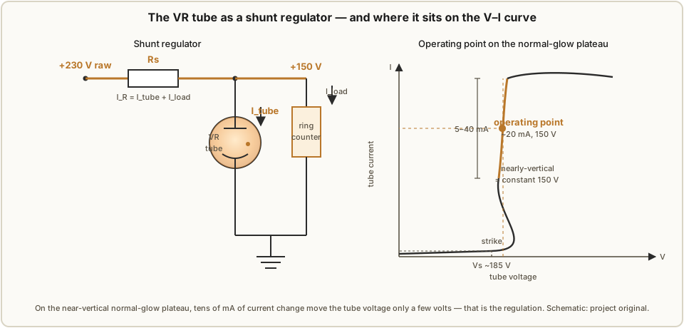
The action is a feedback loop with no moving parts. Suppose the load suddenly draws less current. The regulated node tries to rise; but the instant it does, the tube conducts more (you have moved up its near-vertical plateau) and drops the extra current across the series resistor, pulling the node back down. If the load draws more, the tube conducts less and surrenders its current to the load, and the node holds. The tube is a bottomless (within limits) sink and source of current that keeps the node voltage nailed to the plateau voltage. Because the plateau is genuinely steep — for a good VR tube, tens of milliamps of current change move the terminal voltage only a couple of volts — the regulation is excellent and, unlike an active regulator, utterly silent and unconditionally stable.
8.4.1 Striking versus running voltage
Like every cold-cathode device, a VR tube has two voltages, and the gap between them is the
same hysteresis that makes the neon lamp bistable in Vol 2. The striking (ignition)
voltage Vs is the higher one — the raw rail must exceed it, through the series resistor,
before the tube will ever light. Once struck, the tube settles to its lower running
(operating) voltage Vm, and it is Vm that becomes your regulated rail. For the common
tubes the striking voltage sits roughly 20–35 V above the running voltage: an 0D3/VR150
runs at 150 V but needs about 185 V to strike. This has two practical consequences. First,
your raw DC must clear the striking voltage with margin, not merely the running voltage —
size the transformer accordingly. Second, VR tubes share the neon lamp’s dark effect
(Vol 2): the striking voltage rises, and becomes erratic, in complete darkness. The Mullard
150B2 datasheet is explicit about this, quoting two ignition voltages — one for a specified
ambient light level and a higher one for total darkness. Chassis-mounted VR tubes usually
see enough stray light to strike reliably, but it is a real gotcha in a light-tight
enclosure, and the fix is the same as for the counting lamps: a little ambient light or a
priming glow.
8.4.2 The series resistor sets the current
The one component you actually design is the series resistor Rs between the raw rail
and the tube. It sets how much current flows, and the tube then fixes the voltage. Its value
follows directly from Ohm’s law across the difference between the raw and regulated rails:
Rs = (V_raw − V_reg) / (I_tube + I_load)
where V_raw is the raw DC rail (V), V_reg is the tube’s running voltage (V), I_tube is
the current you want in the tube (A), and I_load is the current the counter draws off the
regulated node (A). The design trick is that the tube current and the load current trade
off against each other through this one resistor. All of I_tube + I_load flows through
Rs; whatever the load does not take, the tube must. So you size Rs for a chosen total
current, then check that as the load swings from zero to its maximum, the tube current stays
inside its rated window. Concretely: with V_raw = 230 V, V_reg = 150 V, and a target
total of 25 mA, Rs = (230 − 150) / 0.025 = 3 200 Ω, so a standard 3 kΩ works. At no
load the tube carries the full ~25 mA; if the load then draws 15 mA, the tube drops to ~10 mA
— still safely on the plateau. Size the resistor’s wattage from P = I² · Rs: at 25 mA that
is 0.025² × 3 000 ≈ 1.9 W, so a 5 W wirewound part gives sensible derating.
8.4.3 Regulation limits
A VR tube is not a laboratory reference, and it helps to know where it falls short. Its regulation is only specified over a stated current window — typically 5 mA to 30 or 40 mA; below the minimum the glow starves and the voltage climbs and gets noisy, and above the maximum the discharge runs into the abnormal-glow region, the voltage rises, the cathode sputters, and tube life shortens dramatically. So the cardinal rule is: keep the tube current inside its window under all load and mains conditions. Within that window the tube still has a small but finite dynamic resistance — the residual slope of the plateau — of order 100–300 Ω, so a change in current does move the output by a volt or two; that is what the datasheet’s “regulation” figure (a couple of volts for the best tubes, up to ~5.5 V for an 0D3) is telling you. There is also a slow drift with tube ageing and temperature, and tube-to-tube spread of a few volts in the running voltage, so if you need an exact voltage you trim it elsewhere — but for holding a neon counter’s rail steady against mains and load wobble, a VR tube is superb, and it does it with a part that itself glows a friendly purple.
8.5 The classic VR-tube table
Seven cold-cathode regulator types cover essentially every rail a neon counter needs. The “0-series” American types come in two package families — the miniature 7-pin 0A2/0B2 and the octal 0A3/0B3/0C3/0D3 — and the European 150B2 (a Mullard/Philips 150 V stabiliser, and the exact part PA3FWM eventually fitted to his neon clock in place of the neon-lamp references he started with). Running voltages, striking voltages, and current windows are the datasheet nominals; individual tubes vary by a few volts.
Table 1 — 8.5 The classic VR-tube table
| Type | Running V_reg | Striking Vs (approx.) | Current window | Package | Notes |
|---|---|---|---|---|---|
| 0A2 | 150 V | ~185 V | 5–30 mA | miniature 7-pin | regulation ~2 V; the go-to 150 V miniature |
| 0B2 | 108 V | ~133 V | 5–30 mA | miniature 7-pin | ~108 V rail; regulation ~4 V |
| 0A3 / VR75 | 75 V | ~105 V | 5–40 mA | octal | lowest common rail; regulation ~5 V |
| 0B3 / VR90 | 90 V | ~115 V | 5–40 mA | octal | 90 V rail |
| 0C3 / VR105 | 105 V | ~133 V | 5–40 mA | octal | 105 V rail; regulation ~4 V |
| 0D3 / VR150 | 150 V | ~185 V | 5–40 mA | octal | 150 V rail; regulation ~5.5 V; the workhorse |
| 150B2 | 150 V | ~170–185 V | ~5–40 mA | miniature 7-pin | Mullard/Philips 150 V; two ignition specs (light/dark); the PA3FWM part |
Two families, two voltages each, essentially: 75/90/105/150 V on the octals and 108/150 V on the miniatures. For a neon ring counter the 150 V types (0A2, 0D3, 150B2) are the natural fit, because 150 V is the rail Luc Small ran his IN-3 ring on and close to PA3FWM’s +151/+157 V. Where you need something odd — 105 V, 90 V — the octals cover it, and where you need more than any single tube gives, you stack them.
8.6 Stacking VR tubes for higher rails and intermediate taps
Because a VR tube simply holds a fixed voltage across itself, you can put two (or more) in series and add their voltages, all fed by a single series resistor from a raw rail tall enough to strike the whole stack. Two 0D3s in series regulate 300 V; an 0D3 stacked on an 0C3 regulates 255 V; and every junction between tubes is itself a regulated tap — the stack gives you a 150 V rail and a 300 V rail from one resistor, or a 105 V rail and a 255 V rail, and so on.
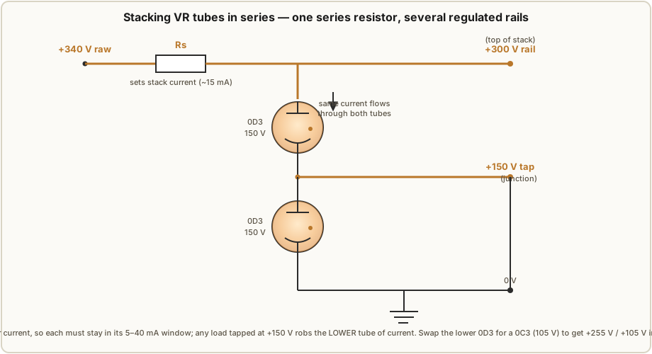
The rule that makes or breaks a stack is that the same current flows through every tube in the series string — it has nowhere else to go. So the series-resistor current must keep all the tubes inside their windows simultaneously, and, more subtly, any load you tap off an intermediate junction is subtracted from the current reaching the tubes below it. In the two-0D3 stack of Figure 8.6, current drawn from the +150 V junction bypasses the lower tube, so if you lean on that tap too hard the lower tube starves below 5 mA and drops out of regulation. The design procedure is therefore to work from the bottom up: pick the series-resistor current so the lowest tube still has ≥5 mA after the worst-case intermediate load, and confirm the top tube stays under ~40 mA at no load. In practice you keep intermediate taps lightly loaded (a few mA) and take the heavy load from the top or bottom of the stack. Stacked VR tubes are exactly how the tall rails for dekatron anodes (Vol 5, often +400 V or more) were regulated in the classic instruments.
8.7 A neon lamp as a crude reference
Before reaching for a proper VR tube it is worth remembering that an ordinary indicator neon is itself a shunt regulator, just a poor one. Sitting on its own maintaining voltage, an NE-2 holds roughly 55–60 V across itself once struck (Vol 2), so a single neon fed through a series resistor makes a crude ~60 V reference, and two in series give a ~110–120 V one. This is genuinely useful for biasing — pre-charging a buffer lamp, setting a threshold — and it costs pennies. Its limitations are exactly the marginal-lamp problems of Vol 3: the maintaining voltage varies several volts from lamp to lamp and drifts with age and temperature, the dynamic resistance is far higher (poorer regulation) than a purpose-built VR tube, and the tiny NE-2 can only pass a milliamp or two before its little electrodes overheat. PA3FWM’s neon clock is the cautionary tale: he began with neon lamps as his supply references and found them not stable enough, ultimately replacing them with a proper 150B2 stabiliser tube. Use a neon as a reference for a rough bias where a few volts of slop is fine; reach for a VR tube when a stiff rail matters — which, for the ring counter itself, it does.
8.8 A worked supply for a neon ring counter
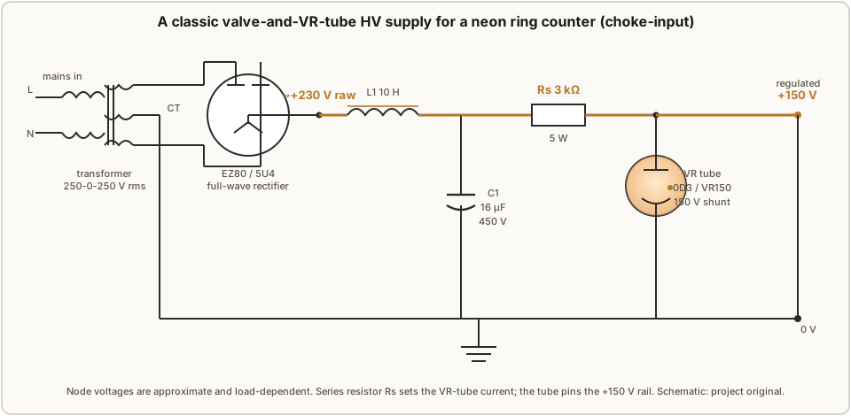
Let us build the whole thing for a concrete case: a 150 V rail for a ten-stage IN-3 ring counter of the kind Vol 13 builds, drawing at most a few milliamps (only one lamp is lit at a time, at Luc Small’s ~800 µA, plus buffer and margin — call it up to 15 mA to leave room for a multi-decade clock). We want the rail regulated and low-ripple. This is the supply drawn in Figure 8.1.
Transformer. A 250-0-250 V RMS centre-tapped secondary, rated ≥ 60 mA, with a separate 6.3 V heater winding for the rectifier valve. Isolated from the mains — always.
Rectifier. An EZ80 full-wave valve (or a pair of 1N4007s if you prefer silicon), feeding the filter. Its slow warm-up conveniently delays the HV until the heaters are up.
Filter — choke-input. A 10 H choke (rated for the full current) followed by a
16 µF / 450 V reservoir capacitor. Choke-input gives V_raw ≈ 0.9 × 250 ≈ 225 V, which
we round to ~230 V for design. The raw ripple, from r ≈ 0.83 / (L·C) = 0.83 / 160 ≈ 0.0052, is about 0.5 %, roughly 1.2 V RMS on the 230 V raw rail.
Regulator. An 0D3/VR150 (or 0A2, or 150B2) from the +150 V node to ground, fed
through a series resistor Rs. Sizing for a total current of ~25 mA:
Rs = (V_raw − V_reg) / I_total = (230 V − 150 V) / 0.025 A = 3 200 Ω → use 3 kΩ.
Its dissipation is P = I² · Rs = (0.025)² × 3 000 ≈ 1.9 W, so specify a 3 kΩ, 5 W
wirewound resistor.
Check the tube window across load. At no load the tube carries the full ~26.7 mA
((230 − 150)/3 000), just under the 40 mA ceiling. At the maximum 15 mA load the tube
carries 26.7 − 15 ≈ 11.7 mA, comfortably above the 5 mA floor. The tube stays in regulation
across the entire load range — the design is sound.
Resulting rail. The output sits at +150 V, regulated. The VR tube’s dynamic
resistance (order ~150 Ω for an 0D3) attenuates the raw ripple by roughly r_d / (Rs + r_d) ≈ 150 / 3150 ≈ 0.048, knocking the ~1.2 V raw ripple down to about 60 mV RMS on the
regulated rail — and it holds that 150 V against mains swings and load changes that would move
an unregulated rail by many volts. Finally, and non-negotiably: fit a bleeder resistor
(a couple of hundred kΩ, a watt or two) permanently across the reservoir capacitor so the
rail discharges within seconds of switch-off. ⚠ That reservoir cap holds a lethal charge; the
bleeder, and a verified discharge before you touch anything, are Vol 14’s discipline and they
start here.
That is a complete, period-correct, buildable supply: transformer, valve rectifier, choke-input filter, one VR tube, one resistor, one bleeder — a stiff +150 V rail with tens of millivolts of ripple, made almost entirely of parts that glow. Vol 9 does the same job with a switching converter the size of a postage stamp; but for a counter built from tubes, there is a real pleasure in a supply that is tubes all the way down.
References
- J. B. Dance, Electronic Counting Circuits (London: Iliffe Books / New York: American Elsevier, 1967) — in the site’s reference library. The canonical treatment of cold-cathode counting supplies and VR-tube regulation.
- P.-T. de Boer (PA3FWM), “A clock using neon lamps as logic elements” — https://www.pa3fwm.nl/projects/neonclock/ (the +151/+157 V rails; neon-lamp references later replaced by a 150B2 stabiliser).
- L. Small, “Neon Ring Counters” (2016) — https://lucsmall.com/2016/10/08/neon-ring-counters/ (the 150 V rail and ~800 µA per-lamp current the worked example is sized around).
- “Voltage-regulator tube,” Wikipedia — https://en.wikipedia.org/wiki/Voltage-regulator_tube (VR-tube family, running/striking voltages, current windows).
- VR-tube datasheets via Frank Philipse’s tube data (frank.pocnet.net): 0A2, 0B2, 0A3/VR75, 0B3/VR90, 0C3/VR105, 0D3/VR150, 150B2.
- EZ80/6CA4 and 5U4/GZ32 rectifier valve datasheets (frank.pocnet.net); classic valve HV-supply practice (choke- vs capacitor-input filtering).
Comments (0)