Neon Ring Counters · Volume 7
Drift, Ageing & How to Mitigate Them
Why a working ring slowly stops working — the five sources of drift, and the mitigations ranked by leverage
The hardest lesson in this whole field is not how to make a neon ring counter work — Vol 4
gives you the equations and a well-binned batch of lamps will step obediently around the
ring on the first evening you power it up. The hard lesson is how to keep it working, because
a neon lamp is never quite finished changing. Pieter-Tjerk de Boer (PA3FWM) built an entire
clock out of neon logic, burned his lamps in, measured and matched them, wired a stiff
regulated supply, and after one to two years the clock became unusable anyway. His own honest
epilogue is the sentence every builder in this field should tattoo somewhere visible:
“apparently, fully characterising the neon lamps requires more quantities than just the
striking and maintaining voltages.” That is the spine of this volume. Everything that follows
is a catalogue of the ways Vs and Vm — and the things Vs and Vm do not capture — wander
over temperature, over hours, and over years, and a ranked toolkit for pushing the day your
ring gives up as far into the future as it will go. This is the volume you will actually keep
open on the bench while you fight drift, so it is organised by leverage: read the sources once,
then live in §7.8 and the checklist in §7.9.
⚠ Everything here happens on a rail between roughly 100 V and 450 V DC, sitting behind a reservoir capacitor that stays lethal after power-off. Vol 14 is the full safety discipline; treat every rail as live until you have proven it discharged with a meter.
7.1 The five sources of drift
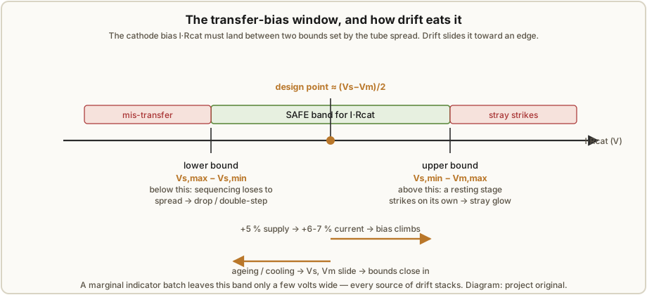
A ring counter lives or dies by margins. Vol 4 showed that reliable stepping needs the cathode
transfer bias I·Rcat to sit inside a window bounded below by the tube-to-tube striking spread
(I·Rcat > Vs,max − Vs,min, so sequencing beats spread) and above by the worst-case
strike-to-maintain gap (I·Rcat < Vs,min − Vm,max, so a resting stage never self-strikes). For
a marginal batch of indicator neons — where the whole Vs − Vm gap is only ~12–20 V — that
safe window can be just a few volts wide before you have done anything at all. Drift is simply
anything that moves either the bias or one of those two bounds. There are five sources worth
naming, and they stack:
- Temperature — both
VsandVmshift with envelope temperature (and with the lamp’s own self-heating), sliding the whole window. - Gas cleanup / ageing — the largest single change, concentrated in the first hours of a lamp’s life, then a slow creep that never fully stops. This is the source that killed the PA3FWM clock.
- Supply-voltage variation — because the anode resistor converts the rail into the lamp
current, a fractional rail shift becomes a magnified fractional shift in
I·Rcat, moving the bias directly across the window. - Light level (the dark effect) —
Vsdrops in light and rises and scatters in darkness, because striking needs a seed of free electrons that ambient light or priming supplies. - Cathode sputtering and contamination — the slow physical erosion and gas-chemistry change that underlies ageing, and eventually the end-of-life failure mode.
The rest of §7.2–7.6 takes each in turn with its physics; §7.7 tells the PA3FWM story as the worked cautionary case; §7.8 is the ranked fix-it list.
7.2 Temperature — the whole window slides
A gas discharge is a thermodynamic process, so its characteristic voltages depend on the gas
density inside the envelope, and gas density depends on temperature. Warm the lamp and the gas
expands (at fixed volume the pressure rises, but the number density the electrons must ionise
is what matters), and both the striking voltage Vs and the maintaining voltage Vm move.
For ordinary neon indicators the temperature coefficient is small — on the order of a few tens
of millivolts per °C, and generally negative, so a lamp that strikes at 90 V on a cold morning
may strike a volt or so lower in a warm rack — but “small” is measured against a safe window
that is itself only a few volts wide. A 20 °C ambient swing between a cold start and a
fully-warmed enclosure can move a bound by half a volt to a volt, which is a meaningful fraction
of the margin you fought for in Vol 4.
Two temperature effects deserve separate mention because they are avoidable. The first is
self-heating: the discharge dissipates I·Vm in each lit lamp — for Luc Small’s 800 µA at a
~40 V maintaining drop that is only ~32 mW, but a densely-packed ring warms its own tubes and
the tubes do not all sit at the same temperature, so self-heating adds a differential shift
between stages, which is exactly the kind of shift that eats matching. The second is
gradient: a lamp near a hot supply resistor, a rectifier valve, or a case wall in the sun
ages and drifts differently from its neighbours. Both point at the same mitigation — keep
currents modest (§7.8.7) and give the tubes a thermally even, ventilated home — and both are
reasons to characterise and bin your lamps (Vol 3) at the temperature the ring will actually
run at, not cold on the bench.
7.3 Gas cleanup and ageing — the big one
This is the source that will defeat you if any of them does. A sealed cold-cathode lamp is not
chemically static: running the discharge slowly changes the composition and pressure of the gas
and the state of the cathode surface. Fresh gas contains trace impurities and the cathode
carries adsorbed layers; the first hours of operation “clean up” the gas — impurities are
gettered onto the electrodes and walls, adsorbed gas is driven off or buried — and during that
cleanup Vs and Vm move substantially. After the initial settling the change slows to a
crawl, but it never quite stops, which is why ageing shows up on both timescales: a fast
transient you can burn out deliberately (Vol 11), and a slow lifelong creep you can only design
margin against.
Ronald Dekker measured this directly, and his numbers are the ones to carry. He took 21 neon
tubes, measured each tube’s Vs and Vm, then aged them for three days at about 1 mA of AC
excitation from a variac, and measured again. Before ageing the batch averaged Vs ≈ 68.8 V
(spread 60–76 V) and Vm ≈ 56.9 V (spread 50–64 V) — a mean gap of only ~12 V, and, damningly,
some tubes had a Vs lower than other tubes’ Vm, which makes reliable ring counting
impossible on its face. After three days the averages had each fallen by about 1.5 V — Vs ≈
67.3 V, Vm ≈ 55.4 V — with the largest movement in the first few hours, exactly the fast
transient. But the gap stayed ~12 V and, crucially, the unit-to-unit spread did not shrink:
ageing moved the whole population down together without tightening it. Dekker’s own verdict on
that batch was that “despite considerable effort it appeared impossible to obtain reliable
counting operation” from ordinary indicator neons — which is the entire argument for switching
tubes with a real 60 V window (Vol 3).
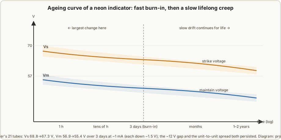
The practical readings from this are three. First, any measurement taken on a fresh lamp is a lie — it will have moved by a volt or more before your ring has run a day, so you must burn-in before you bin (Vol 11 builds the jig). Second, burn-in tightens nothing: it stabilises each lamp near its long-term value but leaves the spread, so binning after burn-in is still mandatory. Third, the slow creep is unbudgeable — no amount of conditioning stops a lamp ageing over years, so the only defence against the long tail is generous margin and, for a long-lived build, planned re-matching or replacement. The switching-tube path (ZA1002) sidesteps most of this by starting with a 60 V window that a couple of volts of lifelong creep barely dents; the indicator-neon path (NE-2/IN-3) never gets that luxury.
7.4 Supply-voltage variation — how a 5 % rail shift eats the window
The supply is the most controllable source of drift and, if you get it wrong, one of the most
damaging, because the anode resistor Ra turns the rail directly into lamp current and the lamp
current sets the transfer bias. Recall from Vol 4 that Ra = (Vsupply − Vlamp) / Inom, so the
operating current is Inom = (Vsupply − Vm) / Ra, and the transfer bias is I·Rcat = Inom·Rcat.
Differentiate and the sensitivity falls out: a fractional change in the rail produces a larger
fractional change in the current, because the whole rail change lands on a numerator
(Vsupply − Vm) that is smaller than the rail itself:
dInom / Inom = dVsupply / (Vsupply − Vm)
Put Luc Small’s numbers in — a 150 V rail into a lower-cluster lamp whose Vm ≈ 40 V, so
Vsupply − Vm ≈ 110 V. A 5 % rail rise is +7.5 V, giving dInom / Inom = 7.5 V / 110 V ≈ 6.8 %.
The transfer bias I·Rcat climbs by that same 6.8 %, so a design point sitting at, say, 14.4 V
(800 µA into an 18 kΩ cathode resistor) moves about a volt — and it moves toward the
stray-strike bound if the rail rises and toward the mis-transfer bound if it sags. A single
volt does not sound like much until you remember the safe window can be only a few volts wide,
and that this supply-driven volt stacks on top of the temperature and ageing shifts that are
moving the bounds at the same time.
There is a second, blunter way the supply bites: the rail must stay comfortably above the
highest Vs in the ring for every stage to be able to strike at all. If a sagging rail dips
toward Vs,max, the tubes at the top of the striking spread stop firing reliably and the ring
drops counts — a hard failure, not a graceful drift. This is why the mitigation ranked first in
§7.8 is a stiff, regulated supply: it is the one source of drift you can very nearly eliminate,
and eliminating it frees the whole margin budget for the sources (ageing, spread) you cannot.
Vols 8 and 9 build the supplies — a VR-tube-regulated valve rail the traditional way, and a
feedback-regulated boost converter the modern way — and both are worth the effort precisely
because of this figure.
7.5 Light level — the dark effect and photosensitivity
A neon lamp will not strike until a stray free electron happens to be present in the gap to seed
the avalanche, and in a clean, dark, unprimed lamp that first electron can be a long and random
time coming. The result is the dark effect: in light, photo-electric emission supplies seed
electrons freely, the lamp strikes promptly and at a repeatable Vs; in darkness the effective
Vs rises and, worse, scatters — the lamp may strike late, or at a voltage tens of volts
above its lit value, or refuse to strike within the time your pulse allows. For a relaxation
oscillator this shows up as jitter; for a ring counter, where the whole trick is that the
pre-biased next stage strikes first and by a predictable margin, an unprimed lamp that strikes
late or high can hand the glow to the wrong stage or drop it entirely.
This is not a small effect and it is not theoretical. The PA3FWM clock’s ring counters were
“rather sensitive to ambient light: in complete darkness, they tend not to work” — the clock
literally stopped keeping time in a dark room until de Boer added illumination. The fix he chose,
two blue LEDs shining on the lamps, is the cheapest possible priming source and belongs in every
build (§7.8.5). The deeper point is that light level is a hidden operating parameter: a ring
characterised and binned under bench lighting may misbehave in a dim display case, and the same
ring may drift between day and night. Priming — ambient light, a permanently-lit lamp or LED, a
keep-alive trickle glow, or the radioactive priming built into tubes like the ZA1002 — removes
the dependence by guaranteeing seed electrons are always present, so the lamp strikes at its
lit-value Vs regardless of the room.
7.6 Cathode sputtering and contamination
Underneath “ageing” is a physical mechanism: ion bombardment of the cathode. Every discharge is
positive ions accelerated onto the cathode surface, and over time that bombardment sputters
cathode material off — atom by atom it erodes the emitting surface and redeposits metal on the
walls and the other electrode. Sputtering changes the cathode’s work function and effective
area, which changes Vm; the sputtered metal getters gas, which changes the pressure and hence
Vs; and the darkening film on the glass (the tell-tale metallic mirror you see on a hard-run
old neon) is the same material, cluttering the optical path and, near end of life, providing
leakage paths. Running a lamp hard — high current, or the abnormal-glow region above the
normal-glow plateau where the discharge spreads and intensifies — accelerates every part of
this, which is the physical reason the modest-current mitigation (§7.8.7) buys life.
Contamination is the same story from the gas side. Outgassing from the electrodes and glass,
and the slow migration of the getter chemistry, shift the Penning mixture away from its designed
balance; a lamp whose argon fraction has changed strikes and maintains at different voltages
than when it left the factory. None of this is captured by a one-time Vs/Vm measurement,
which is exactly why de Boer found that two matched voltages were not enough to predict a lamp’s
behaviour: two lamps identical on the meter can be at different points on their sputtering-and-
contamination trajectories, and will diverge with use. Sputtering is also the end-of-life
mechanism — eventually the cathode is too eroded or the gas too far gone, and the lamp strikes
erratically or not at all. There is no mitigation for wear-out except starting with robust tubes,
running them gently, and being willing to replace them.
7.7 The cautionary tale — the PA3FWM neon clock
It is worth telling the whole PA3FWM story once, because it is the most honest reliability
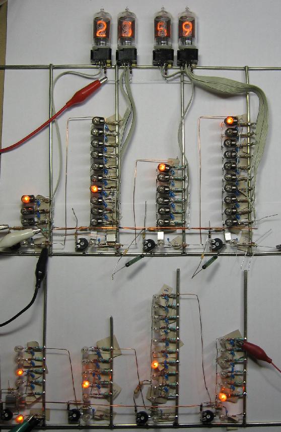
account in the hobby and it touches every source above. De Boer set out to build a clock in
which neon lamps were the logic — eight ring counters (dividers ÷10, ÷5, ÷10, ÷6 turning
50 Hz mains into a 1-per-minute tick, then time counters ÷10, ÷6, ÷10, ÷3 for minutes,
tens-of-minutes, hours and tens-of-hours), the count read out by driving nixie tubes through
light-dependent resistors, all on +151 V and +157 V rails later cleaned up with a 150B2
stabiliser tube. He did everything this volume recommends. He burned the lamps in before
measuring, precisely because “the striking and maintaining voltages of the lamps change quite
much during their first hours of operation.” He matched them on Vs and Vm. He ran a
regulated supply.
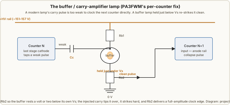
And it still fought him at every turn. Modern indicator lamps have too small a Vs − Vm window
to cascade one counter straight into the next, so he had to add an extra neon “buffer” lamp
per counter, biased to just under its striking voltage so that a small pulse can strike it —
the carry-amplifier stage of §7.8.8. The rings would not run in the dark, so he added the blue
LEDs of §7.5. Individual lamps misbehaved in ways no meter reading predicted: one lamp was
“unreliable in the buffer stage despite matching specifications”; another “worked at ~1 Hz pulse
rates but failed when receiving pulses only hourly” — a rate-dependent failure that no static
Vs/Vm pair can describe; and some selected lamps simply “acted weird and needed to be
replaced.” Then the long tail arrived: “apparently, these bulbs continued ageing, and more
parameters than just those two voltages play a role,” and after one to two years the clock
became unusable and was retired. The lesson is not that neon logic is hopeless — it kept time for
a year or two, which is a triumph — but that selection and burn-in buy you a good start, not a
permanent one, and that the honest design posture is maximum margin plus a willingness to
re-match. Hold this story in mind while reading the mitigations: every one of them is something
de Boer either did or wished he had leaned on harder.
7.8 The mitigations, ranked by leverage
Drift is a stack of shifts against a narrow window, so the winning strategy is to spend your effort where it widens the window most. What follows is ranked: do the high-leverage items even on a quick build, and add the lower ones as the build’s ambition (and expected lifetime) grows.
7.8.1 A stiff, regulated supply (highest leverage)
Because §7.4 showed the rail feeds straight through to the transfer bias with gain, regulating the supply is the single most effective thing you can do, and it is the source of drift you can very nearly delete rather than merely reduce. Hold the rail to ~1 % and its contribution to bias drift drops from the ~7 % a wandering unregulated supply can cause to something you can ignore, freeing the whole margin budget for ageing and spread. The traditional answer is a VR-tube shunt regulator (a 0A2, 0D3, or the PA3FWM’s 150B2) which pins the rail at its own maintaining voltage; the modern answer is a boost converter with a feedback divider holding the set-point. Either way, add a bleeder across the reservoir for safety and set-point stability. Build details are in Vols 8 (traditional) and 9 (modern) — this is where they earn their pages.
7.8.2 Binning and matching
If you cannot make the lamps identical, at least group the ones that already are. Measuring each
lamp’s Vs and Vm and designing Rcat/Ra per cluster is the difference between a ring that
steps and one that stalls, because the lower bound of the safe window is the striking spread
Vs,max − Vs,min — shrink the spread by binning and the window widens directly. Dekker’s data is
the warning that binning is necessary but not sufficient (the spread persists through ageing) and
Luc Small’s three clusters (Lower/Middle/Upper, each a few volts wide) are the worked example.
The full procedure lives in Vol 3, and the measurement station is part of the Vol 11 jig.
7.8.3 Burn-in before final measurement
Because the largest ageing shift happens in the first hours (§7.3), measure after it, not before. Run every new or NOS lamp at rated current for hours to days — Luc Small used 48 hours, de Boer burned-in before measuring — so the fast transient is spent and your binning reflects the lamp’s stable value rather than its shipping value. Burn-in also weeds out infant-mortality failures before they are soldered into a ring. It tightens nothing (bin afterwards) and stops nothing long-term (the slow creep continues), but it removes the one shift big enough to move a freshly-tuned bias clean out of its window in a day. Vol 11 builds the burn-in/ageing jig.
7.8.4 Centre the bias, and prefer large-window tubes
Set I·Rcat ≈ (Vs,avg − Vm,avg) / 2 so the operating point sits in the middle of the safe
window, as far as possible from both the stray-strike bound above and the mis-transfer bound
below — that way a drift of a volt in either direction from any source still lands inside the
window. This is free; it is just choosing Rcat well (Vol 4). Far more powerful, if you can get
the tubes, is to start with a wide window: a Philips ZA1002 switching tube offers ~60–65 V
between Vs ≈ 170 V and Vm ≈ 105 V, so a couple of volts of lifelong creep barely register,
whereas an NE-2’s ~12–20 V window is a knife-edge from the start. The catch (Vol 3) is that
ZA1002s are NOS-only and their tritium priming has decayed — 12.3-year half-life means a
60-year-old tube retains only ~1/64 of its priming and can strike erratically anywhere from
170 V to 220 V, which is the dark effect (§7.5) returning through the back door and an argument
for adding external priming even to a “primed” tube.
7.8.5 Priming — kill the dark effect, speed the strike
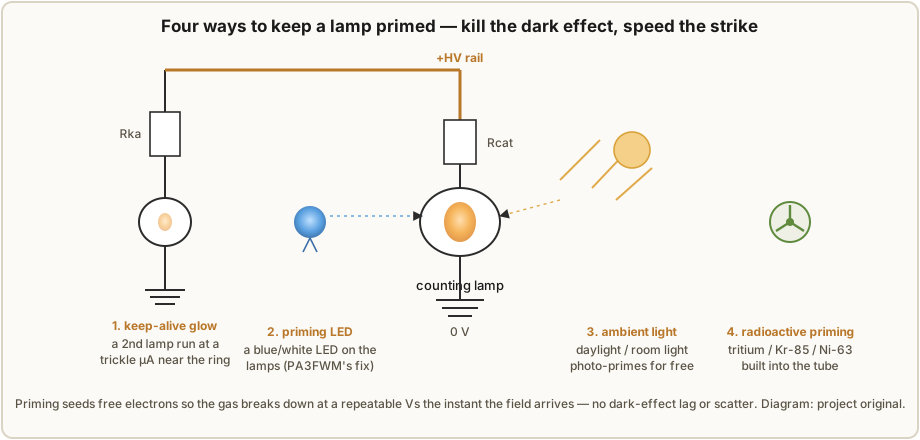
Guarantee that a seed electron is always available and the lamp strikes at its repeatable,
lit-value Vs regardless of the room, removing both the dark-effect scatter (§7.5) and much of
the striking delay that limits speed (Vol 6). There is a ladder of options, cheapest first:
ambient light (free, but not dependable in a dark case); a permanently-lit priming lamp or
LED aimed at the ring — de Boer’s two blue LEDs are the canonical fix and cost pennies; a
keep-alive glow, a second neon run at a sub-visible trickle current (tens of µA through a
large series resistor) sitting near the counting lamps to flood the neighbourhood with photons
and ions; and radioactive priming built into purpose-made tubes (tritium, Kr-85, Ni-63,
thorium), which is why a fresh ZA1002 strikes in under a millisecond — with the caveat above that
decayed tritium undoes it. For any indicator-neon ring, fit a priming light; it is the highest
reliability-per-cent you can spend after the supply.
7.8.6 Low-TC, stable passives
The bias you centred so carefully is I·Rcat, a product of a current and a resistance, and both
the cathode resistors and the coupling capacitors drift if you buy the wrong parts. A carbon-
composition resistor has a large voltage coefficient and a poor temperature coefficient and drifts
and adds noise at the kilohm-at-hundreds-of-volts duty these circuits ask of it; a metal-film
resistor holds its value and its 1 % tolerance is what lets you centre a tight bias at all. On the
capacitor side, a high-K ceramic (X7R/Y5V) or an electrolytic in a coupling or timing slot brings
leakage and dielectric absorption that show up as bias creep and transfer jitter; polypropylene,
polystyrene, or C0G/NP0 hold their value and their charge. Choosing stable passives converts a
drift source into a non-source. Vol 10 is the full treatment of dielectric choice, voltage
coefficient, and derating.
7.8.7 Keep currents modest
Every source that involves the discharge itself — self-heating (§7.2), sputtering and
contamination (§7.6) — scales with how hard you run the lamp. Choosing the lower end of the
sensible current range (Luc Small’s 800 µA rather than several mA) reduces self-heating and its
differential-between-stages shift, slows the sputtering that ages the cathode, and keeps the
lamp on the flat normal-glow plateau rather than pushing into the abnormal-glow region where
erosion accelerates. The cost is a slightly smaller I·Rcat for a given Rcat and a slightly
dimmer glow, both easily recovered by design. Modest current is close to free life-extension.
7.8.8 Buffer / amplifier lamps for reliable carry
When one ring must clock the next — a divider chain, or a multi-digit clock — the carry pulse a
modern lamp can deliver is often too weak to reliably collapse the next counter’s rail, and
direct coupling fails intermittently as margins drift. The fix, straight from the PA3FWM clock,
is a buffer lamp per counter: an extra neon biased by a divider to sit a volt or two below
its own striking voltage, so the weak carry pulse coupled onto it is just enough to tip it over
Vs. It strikes hard, and its cathode resistor delivers a full-amplitude, well-defined clock
edge to the next stage. The buffer regenerates the pulse the way a logic buffer restores a weak
digital edge, decoupling one counter’s tired margins from the next. It is not free — it is
another lamp, with its own drift and its own dark effect (de Boer had one misbehave despite
matching) — so prime it, bin it, and burn it in like any other; but for any cascade it is the
difference between a chain that carries and one that silently loses a digit.
7.9 The drift-hardening checklist
Ranked by leverage, this is the bench checklist to run against any ring before you trust it to run for more than an evening. The right-hand column names the volume that builds the fix.
Table 1 — 7.9 The drift-hardening checklist
| # | Do this | Attacks | Cost / effort | Where |
|---|---|---|---|---|
| 1 | Regulate the supply to ~1 % (VR tube or feedback boost); add a bleeder | Supply drift (§7.4) — the highest-gain source | Medium — a real build | Vols 8, 9 |
| 2 | Bin and match lamps into clusters; design Rcat/Ra per cluster | Striking spread — the lower window bound | Medium — measure every lamp | Vol 3, 11 |
| 3 | Burn-in every lamp (hours–days) before measuring, then re-bin | The fast ageing transient (§7.3) | Low effort, long wait | Vol 11 |
| 4 | Centre the bias at (Vs−Vm)/2; prefer wide-window tubes (ZA1002) | Both window bounds at once (§7.8.4) | Free (Rcat choice) / tube cost | Vol 4, 3 |
| 5 | Prime the ring — a lit LED/lamp, keep-alive glow, or ambient light | The dark effect (§7.5); slow striking | Pennies (an LED) | §7.8.5 |
| 6 | Use stable passives — metal-film R, polypropylene/C0G C | Passive drift, jitter, bias creep (§7.8.6) | Low — buy the right part | Vol 10 |
| 7 | Run modest current (~sub-mA); stay on the normal-glow plateau | Self-heating, sputtering (§7.2, §7.6) | Free (design choice) | Vol 4 |
| 8 | Add buffer lamps for every counter-to-counter carry | Weak-carry cascade failure (§7.8.8) | One lamp per carry | §7.8.8 |
| — | Characterise at operating temperature, not cold on the bench | Temperature offset in binning (§7.2) | Free (measure warm) | Vol 3 |
| — | Plan to re-match / replace over years; log Vs/Vm at intervals | The unbudgeable slow creep (§7.3, §7.7) | Ongoing attention | this vol |
The honest summary is the one PA3FWM leaves us with: the first eight items buy you a ring that works well and lasts a year or more, and the last item is the admission that a neon lamp is never finished changing — so a build meant to run for the long haul needs not just good design but a maintenance posture. Do items 1–5 and even a marginal indicator-neon ring becomes usable; skip the supply regulation or the priming and no amount of the rest will save it.
References
- R. Dekker, “A Neon Ring Counter” / Ring Counter Variations — https://www.dos4ever.com/ring/ring.html
(the 21-tube 3-day ageing experiment:
Vs68.8 → 67.3 V,Vm56.9 → 55.4 V, ~12 V gap and spread both persisting; the ZA1002 tritium-decay data; the transfer-bias design bounds). - P.-T. de Boer (PA3FWM), “A clock using neon lamps as logic elements” — https://www.pa3fwm.nl/projects/neonclock/ (burn-in before measurement; per-counter buffer lamps; the dark-effect blue-LED fix; +151/+157 V rails and the 150B2; the rate-dependent lamp failures; “fully characterising the neon lamps requires more quantities than just the striking and maintaining voltages”).
- L. Small, “Neon Ring Counters” (2016) — https://lucsmall.com/2016/10/08/neon-ring-counters/ (the 48-hour burn-in; the three measured clusters; the 150 V / 800 µA / 18 kΩ / 120 kΩ / 100 nF worked values used here for the supply-sensitivity calculation).
- J. B. Dance, Electronic Counting Circuits (London: Iliffe Books / New York: American Elsevier, 1967) — in the site’s reference library (cold-cathode ageing, sputtering, and the classic regulation practice underneath all three sources above).
Comments (0)