Neon Ring Counters · Volume 6
Frequency Division & Accuracy
Why a neon ring is an exact integer divider, where the errors really live, and the Philicorda organ that made music out of it
Ask how accurately a neon ring counter divides a frequency and you have asked a
question with a surprisingly sharp two-part answer, and getting the two parts straight is
the whole point of this volume. The tidy part is that a ring counter is a counting
divider: it counts input pulses and emits one output pulse for every N it receives,
so the division ratio is the integer N — not N plus a little, not N on a good day,
but exactly N — and it stays exactly N for as long as the ring counts reliably. A
neon divider therefore adds no frequency error of its own: feed it a source of f_in
and its output is f_in/N to the same precision as f_in itself. That is why, in the
Philips Philicorda organ we dissect at the end of this volume, the pitch stability of
every note is set by the top-octave master oscillator and not by the banks of neon
tubes dividing it down. The untidy part — and the part a reader who has actually run one
of these will nod grimly at — is that “for as long as the ring counts reliably” is doing
enormous work in that sentence. A cold-cathode ring is only as trustworthy as its tube
margins, and when those margins erode two distinct defects appear: reliability faults
(a tired stage that drops or doubles a transfer, corrupting the count) and jitter
(the transfer instant wandering in time, smearing the output edges). Neither is a change
in the ratio; both are ways the exact ratio can be broken or blurred. This volume pulls
those threads apart, quantifies each, distinguishes the ring from a fundamentally riskier
kind of divider that can land on a wrong ratio, works the PA3FWM mains-to-minute divider
chain as the canonical cascade, and then tells the Philicorda story.
6.1 A ring is a counting divider — and counting divides exactly
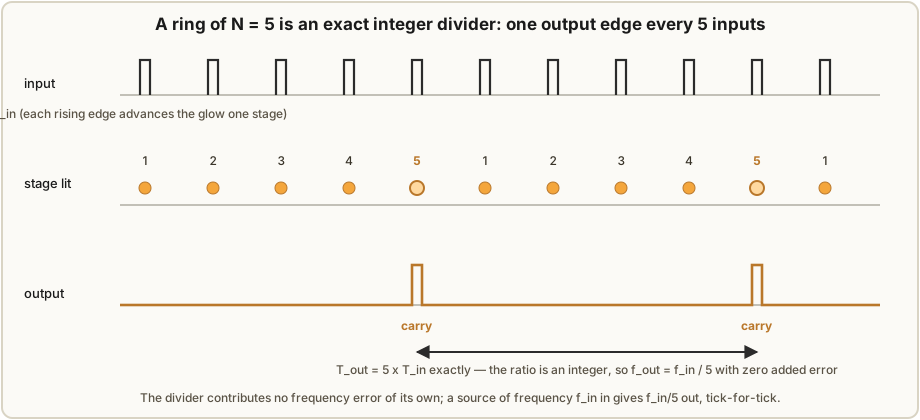
Recall the mechanism from Vol 4: N neon stages share a common anode, exactly one is lit,
and each input pulse extinguishes the lit stage and lights the next one along, so the glow
marches around the ring one place per pulse. Tap a fixed stage — say the last one — and
that stage lights once every time the glow completes a full lap, which is once every N
input pulses. That single fact is the entire theory of neon frequency division: one
output event per N input events. There is no averaging, no phase-locked loop settling,
no analogue quantity that can be a few percent off. The output is a consequence of
counting, and counting to N gives you N — an integer, by construction.
Put it as an equation, defining every term. Let f_in be the input pulse rate in hertz,
N the number of ring stages (a positive integer), and f_out the rate at the carry tap.
Then
f_out = f_in / N — with N exact.
Contrast this with an analogue divider such as a resonant tank or a regenerative mixer,
where the output frequency depends on component values that carry tolerances (±5 %
capacitors, temperature-drifting inductors) and therefore inherit those tolerances as a
frequency error. The ring has no such term. Its N is set by how many stages you wired,
a quantity known to infinite precision because you can count the lamps by eye. If the ring
counts at all, it counts to the right number. This is the same reason a digital
flip-flop divider (Vol 6.7) is trusted to divide a crystal down to a wristwatch’s one
pulse per second: division by counting is division by an integer, and integers do not
drift.
So the headline is genuinely reassuring: the neon stage contributes nothing to the frequency accuracy of the divided output. All of the frequency accuracy you get out is frequency accuracy you put in. If you want a pitch stable to a few parts per million, you put a few-parts-per-million source in front of the ring; the ring will hand you that stability divided down, untouched. Everything difficult about neon dividers is therefore not about the ratio. It is about the two ways the counting itself can misbehave, which occupy the next two sections.
6.2 Reliability: the ratio is exact, but a mis-count breaks it
The first way to spoil a perfect ratio is to break the counting. A ring divides by N
only if it advances exactly one stage per input pulse — no more, no less. Two failure
modes violate that, and both were catalogued the hard way by the builders in our spine
sources (Vol 1’s Dekker, Luc Small, and PA3FWM).
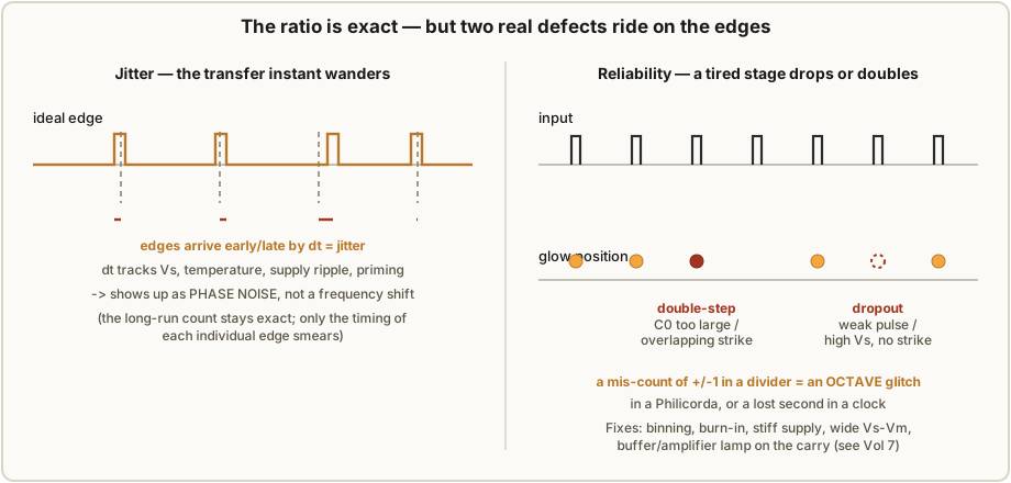
A dropout happens when an input pulse fails to move the glow: the pre-biased next stage
does not reach its striking voltage Vs, either because the carry pulse was too weak or
because that particular tube’s Vs has crept up with age (Vol 7). The glow stays put, the
ring has counted one input as zero, and the divided output is now one pulse short over
that lap. A double-step is the opposite: a single input advances the glow two stages,
because the coupling capacitor C0 was oversized (Vol 4’s warning) or two adjacent tubes’
margins overlapped so that extinguishing one primed two neighbours into striking. Now the
ring has counted one input as two, and the output runs one pulse long.
Notice the character of the damage. A dropout or double-step is a ±1 integer error in
the count, and in a divider a ±1 count error is not a subtle few-cents detuning — it is a
gross, discrete event. In a clock (the PA3FWM machine of §6.5) it is a lost or gained
second that then propagates up the whole chain. In a musical octave divider (the Philicorda
of §6.6) a ÷2 stage that momentarily divides by 1 or by 4 throws the note a whole
octave — an unmistakable glitch, not a wobble. This is the crucial accuracy nuance and
worth stating flatly: when a neon divider fails, it fails by an octave (or a whole
count), never by a few parts per million. The frequency you get is either dead right or
conspicuously, discretely wrong. There is no graceful middle where the pitch simply drifts
sharp, because there is no analogue quantity in the count path to drift.
The mitigations are exactly the disciplines the rest of this series preaches, and they all
serve reliability, not ratio: bin your tubes so every stage has a comfortable
Vs−Vm window (Vols 3, 11); burn them in first so their voltages have stopped moving
(Vol 11); run a stiff, regulated supply so the margins do not sag under load (Vols 8,
9); centre the cathode bias at (Vs−Vm)/2 and prefer wide-window switching tubes like
the ZA1002 (~60 V window versus an NE-2’s marginal ~12–20 V); and where a weak modern-lamp
carry pulse cannot reliably clock the next stage, add a buffer/amplifier lamp on the
carry, biased just below its strike voltage so a small pulse tips it over (the PA3FWM fix,
§6.5). None of these touch the ratio — the ratio was always exactly N. They keep the
ring counting so that the exact ratio is actually delivered.
6.3 Jitter: the ratio is exact, but the edges wander
The second defect is subtler and does not corrupt the count at all. Even a ring that never
drops or doubles a transfer does not place its output edges at perfectly even intervals.
The instant at which a stage strikes depends on how fast the anode voltage recovers through
Ra, on the exact Vs of that tube at that moment, on the temperature, on supply ripple,
and on how well-primed the gas is (the photosensitivity and dark-effect of Vol 2). All of
those quantities fluctuate slightly pulse to pulse, so the transfer instant wanders in
time by some small Δt. That timing uncertainty is jitter, and on the output
waveform it shows up as phase noise — the edges are in the right place on average,
but each individual edge arrives a little early or a little late.
The distinction that matters for accuracy: jitter is not a frequency error. Averaged
over many cycles the count is still exactly N, so the long-term frequency f_out = f_in/N is untouched — over a minute, a ÷3000 chain still delivers exactly one pulse per
minute even if every individual edge trembled. What jitter degrades is the short-term
purity of the edges: the cycle-to-cycle period is T_out ± Δt. In a clock that is
invisible (a wristwatch does not care that its one-per-second edge arrived a microsecond
early). In audio it is audible only as a faint noise or “grain” on the tone, not as a pitch
error — which is again why the Philicorda’s tuning is set by its oscillators while the
neon dividers contribute, at worst, a little textural roughness. It is helpful to keep the
two-axis picture of Figure 6.2 in mind: reliability is whether the count is right (a
discrete, catastrophic axis), and jitter is how cleanly each correct edge is placed (a
continuous, cosmetic axis). Neither is a ratio error, and that is the recurring theme.
It is worth putting a rough number on the jitter so its scale is concrete. The transfer
instant is set by how quickly the anode recovers to Vs after the input pulse, which is an
Ra·C charging edge; a small fractional wobble in Vs maps to a proportional wobble in
the crossing time. With Dekker’s values (Ra ≈ 82 kΩ, a stray-plus-coupling capacitance of
order tens of nanofarads) the recovery time constant is on the order of a millisecond, so a
Vs that flickers by even 1 % — entirely plausible for an ageing indicator neon in changing
light — translates to a transfer-timing wander of order tens of microseconds. Against a
per-stage period near the ~1 kHz ceiling (1 ms) that is a percent-level phase smear on each
edge, and against a slow output (a 1-per-second or 1-per-minute clock tick) it is utterly
negligible. That is the right intuition: neon jitter is large compared with a crystal
oscillator’s but tiny compared with the intervals a neon divider is usually asked to mark,
which is why it is a cosmetic defect in practice and never a timekeeping one. A well-primed,
wide-window switching tube on a clean rail brings the figure down further; a starved,
dark-adapted NE-2 pushes it up and, past some point, tips over from mere jitter into the
outright dropouts of §6.2.
Jitter is fought with the same stiff-supply-and-priming hygiene as reliability, plus one
extra: keep the anode recovery fast and repeatable. A well-defined Ra·(stage
capacitance) recovery, a clean regulated rail with low ripple, and reliable priming (a
keep-alive glow, ambient light, or a primed switching tube such as the tritium-primed
ZA1002 that strikes in under 1 ms) all shrink Δt. Low-leakage, low-dielectric-absorption
coupling capacitors (Vol 10 — polypropylene or C0G, never electrolytic or high-K ceramic)
keep the transfer timing from wandering as the caps’ effective value shifts. But the ceiling
is physical: cold-cathode deionisation takes on the order of a millisecond, which is both
why a neon ring tops out near ~1 kHz per stage (Vol 2) and why its edges will never be
as crisp as a silicon flip-flop’s. You divide accurately in ratio but softly in time.
6.4 A true counting divider vs. an injection-locked one
Here is the failure mode a ring counter is gloriously immune to, and understanding why is
the deepest part of the accuracy story. There is an entirely different family of dividers —
injection-locked or regenerative dividers — that produce a sub-harmonic not by
counting but by pulling a free-running oscillator into step with a drive signal. A relaxation
oscillator (including a bare neon-lamp relaxation oscillator, Vol 2) that free-runs near
f_in/N will, when you inject the drive f_in, lock to the exact sub-harmonic f_in/N
as long as f_in/N falls inside its capture (“lock”) band. It looks like a divider and, in
its lock band, it is one.
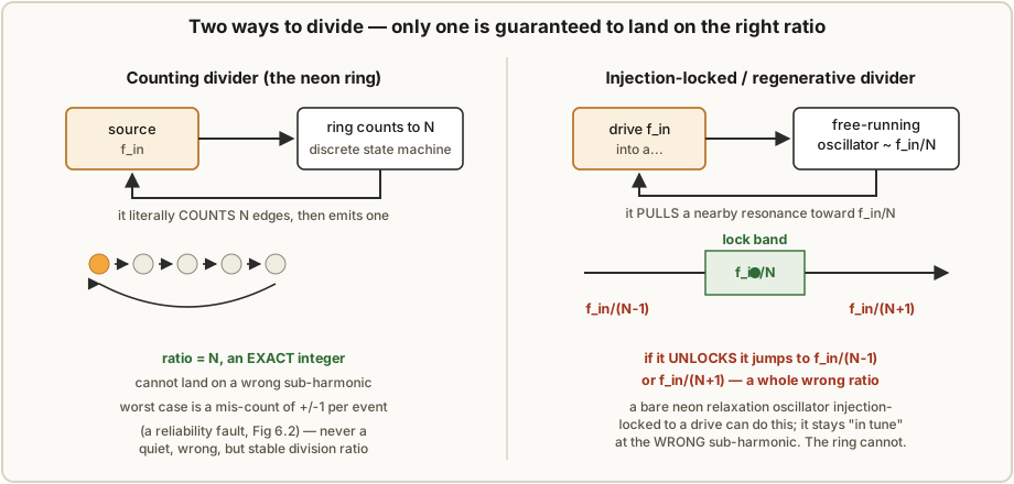
The danger is what happens at the edges of that band. If the drive amplitude sags,
temperature shifts the free-running frequency, or the supply moves, an injection-locked
divider can unlock and re-lock on a different sub-harmonic — jumping from f_in/N to
f_in/(N−1) or f_in/(N+1). It does not glitch once and recover; it settles, quietly and
stably, on the wrong ratio, and it can stay there looking perfectly healthy. That is a
qualitatively worse failure than anything a ring can do, because it is a wrong frequency
that is stable — exactly the thing you cannot catch by ear or by a casual scope glance.
A counting divider cannot do this. The ring has no free-running frequency to be pulled;
it is a discrete state machine that emits a carry only after N genuine input events. Its
ratio is topologically fixed at N by the number of stages. Starve it, and it does not
slide to N−1; it drops or doubles a single transfer (§6.2) and then resumes dividing by
N. The distinction is worth memorising: an injection-locked divider can be quietly wrong
about the ratio; a counting divider can only be momentarily wrong about the count. For
anything where the ratio must be trusted — a clock, an organ’s octaves — you want a counting
divider, and the neon ring is one. (This is also why the Philicorda uses ring-style ÷2
tubes rather than injection-locked sub-oscillators: an organ that could silently drop a note
to the wrong octave under a warm-up transient would be unusable, whereas one that occasionally
glitches audibly is merely charming.)
6.5 Building and cascading rings: the PA3FWM ÷10, ÷5, ÷10, ÷6 chain
The practical craft of neon division is (a) building single rings of the ratio you need and
(b) cascading them so each ring’s carry clocks the next. Any integer N is available: a
ring of N stages divides by N. So ÷2 is a two-stage ring (the Philicorda’s octave
tube), ÷5 a five-stage ring, ÷6 a six-stage ring, ÷10 the classic decade — and a
dekatron (Vol 5) is simply a ten-stage ring integrated into one envelope, dividing by 10
with a carry tap. To divide by a composite number you factor it and cascade: ÷3000 = ÷10 × ÷5 × ÷10 × ÷6. Because every stage divides exactly, the cascade divides exactly by the
product — the errors do not accumulate, because there are no ratio errors to accumulate.
What can accumulate is unreliability: a chain is only as reliable as its least-reliable
stage, and a dropped carry anywhere corrupts everything downstream.
Building each ratio is just choosing the stage count and then applying the same Vol 4 design
math to every stage regardless of ratio — the resistor and capacitor values follow from the
tube’s Vs/Vm and the chosen current, not from N. A few practical notes on the common
ratios:
Table 1 — ratios
| Ratio | Stages | Build notes | Where it shows up |
|---|---|---|---|
| ÷2 | 2 | The minimum ring; two stages ping-pong. The octave-down cell — the Philicorda’s ZA1001 tube (§6.6) and the flip-flop’s direct analogue. | Organ octave dividers |
| ÷5 | 5 | An odd-length ring; carry taps the fifth stage. Pairs with a ÷2 to make ÷10. | PA3FWM 5 Hz→1 Hz stage |
| ÷6 | 6 | The sexagesimal workhorse — seconds→minutes and minutes→hours in any clock. | PA3FWM, and every 60-count |
| ÷10 | 10 | The decade; ten stages, or one dekatron (Vol 5) doing the same job in one envelope with a numbered dial. | Decade scalers, PA3FWM |
Two rules make cascades behave. First, buffer the carry: a ring’s carry pulse is weaker
than its input, so between stages insert the biased buffer lamp of §6.2/§6.5 (or, in period
practice, a trigger tube or a small pulse transformer) so the next ring sees a clean, full-
amplitude strike. Second, factor for reliability, not just arithmetic: ÷3000 could in
principle be one 3000-stage ring, but nobody builds that — you cascade short, individually
reliable rings (÷10 × ÷5 × ÷10 × ÷6) so each stage has few tubes to keep in margin and a
fault is localised. Because each ring divides exactly, any factoring of N gives the same
exact overall ratio; the only thing the factoring changes is how reliable and how serviceable
the chain is.
Pieter-Tjerk de Boer’s (PA3FWM) silicon-free neon clock is the definitive worked cascade, and it is the one to study. Its timebase takes the 50 Hz mains as a frequency reference and divides it down to one pulse per minute through four cascaded neon ring counters — first ÷10 to 5 Hz, then ÷5 to 1 Hz (one pulse per second), then ÷10 to 0.1 Hz, then ÷6 to one pulse per minute. Four more ring counters (÷10, ÷6, ÷10, ÷3) then count the minutes, tens-of-minutes, hours and tens-of-hours for the display, so the whole clock is eight neon rings and not a transistor in sight.
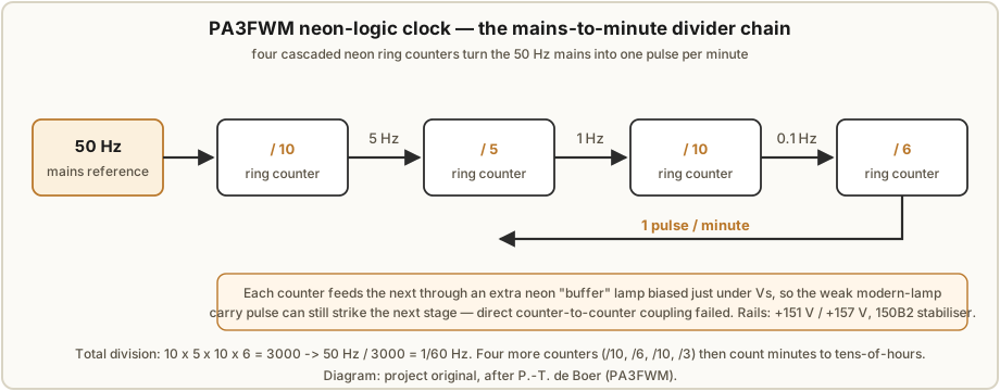
The number that must agree across this whole series: 10 × 5 × 10 × 6 = 3000, and
50 Hz ÷ 3000 = 1/60 Hz, exactly one pulse per minute. And because the mains frequency in
Europe is held to a tight long-term average by the grid operators, that 1/minute pulse
inherits excellent long-term accuracy — the neon rings pass the grid’s timekeeping through
untouched, dividing by an exact 3000. The clock keeps good time not despite the neon
dividers but because they add no error to a good reference.
Two engineering details from that build deserve emphasis because they are exactly the
reliability-vs-ratio lessons of §6.2. First, cascading modern lamps directly did not
work: the carry pulse a ring of ordinary neon bulbs produces is too weak to reliably
strike the first stage of the next ring. De Boer’s fix was an extra neon “buffer” lamp per
counter, biased to sit just below its striking voltage so that a small carry pulse tips it
over and it delivers a clean, strong pulse to the next stage — a neon amplifier, in effect.
Second, the supply had to be stiff: he ran +151 V and +157 V rails, and later
replaced a neon-reference regulator with a proper 150B2 cold-cathode stabiliser tube
(Vol 8) precisely so that supply movement would not eat into the tube margins and provoke
the drop/double faults of §6.2. And the honest coda — told in full in Vol 7 — is that even
with binning, burn-in, buffers and a regulated rail, the clock became unusable after one
to two years as the lamps kept ageing: “more parameters than just those two voltages play
a role.” That is not a ratio failure (the arithmetic ÷3000 was always exact); it is a
reliability failure, the count itself finally becoming untrustworthy. It is the whole
volume in one anecdote.
6.6 The Philicorda: an organ voiced by neon dividers
The most charming application of neon frequency division is not a clock at all but a musical
instrument: the early all-valve Philips Philicorda electronic organ. The headline
model for our purposes is the AG7500 (introduced 1963; the radiomuseum listing dates the
production unit to the mid-1960s), a 49-key single-manual organ whose tone-generation was,
astonishingly for its era, built without transistors — using valve oscillators and neon
tube frequency dividers, right at the moment the transistor was taking over electronic
music. (Hackaday’s July 2026 write-up, “The Organ That Forgot To Use Transistors,” is a good
popular tour of exactly this quirk.) The full deep dive on the instrument lives in the
sibling project ../Philicorda/; here we care only about how the neon division works and
why it sets none of the pitch.
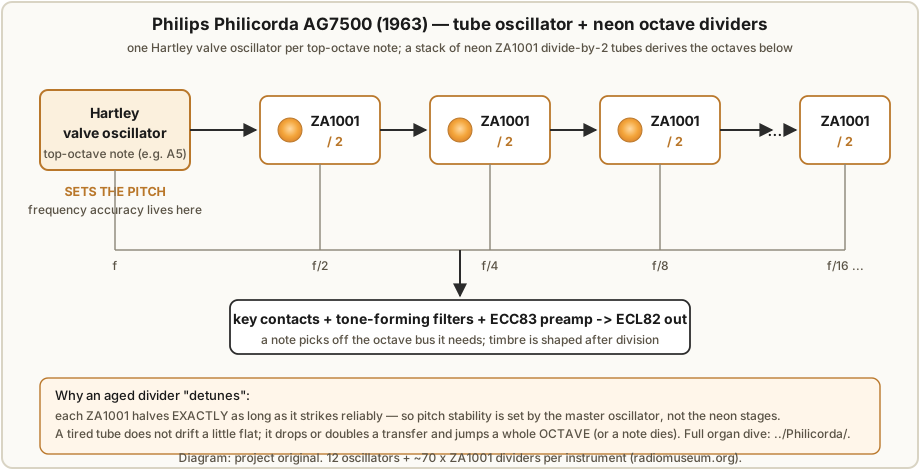
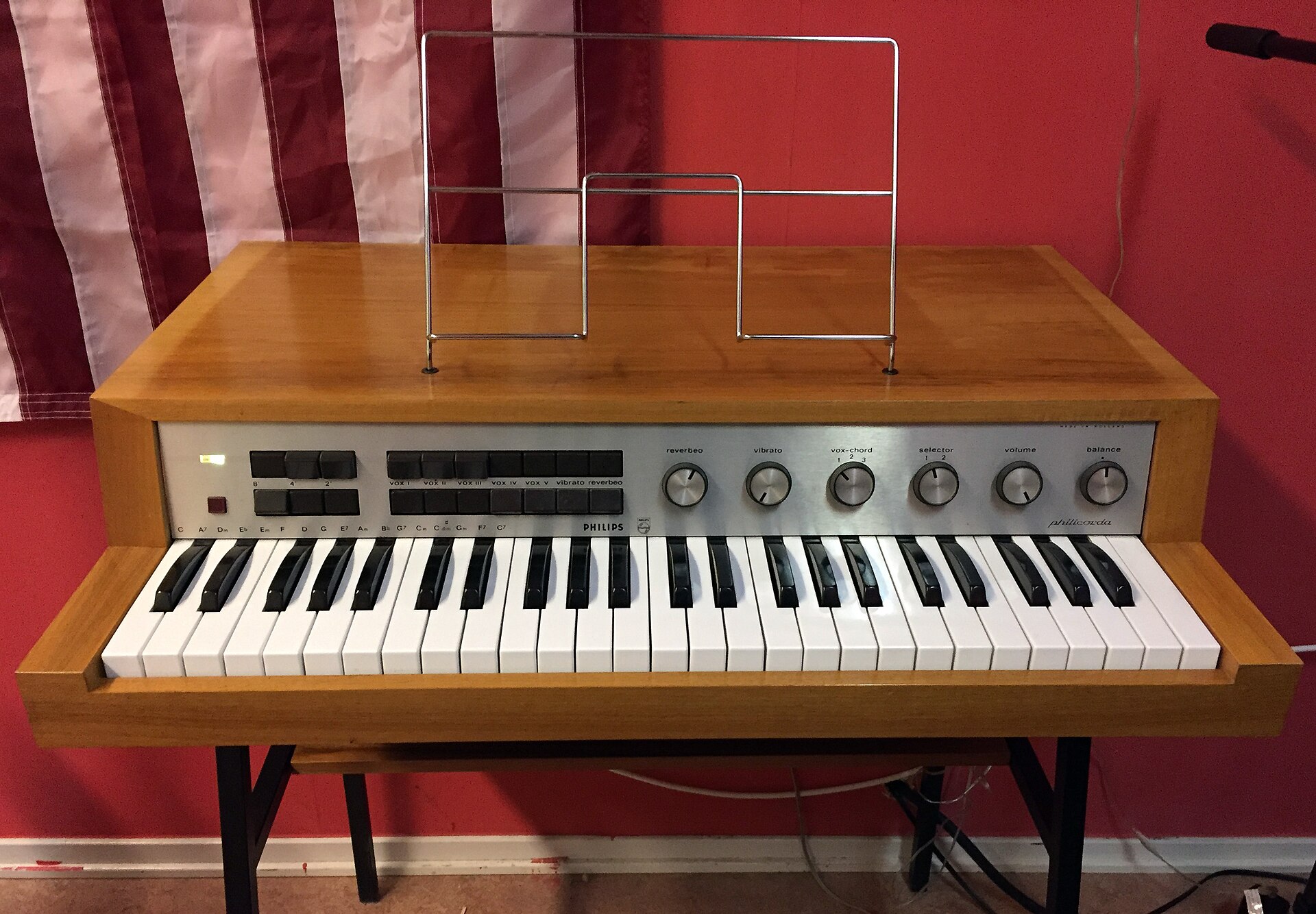
../../Philicorda/ dive. Photo: Kuriosatempel, CC BY-SA 4.0, via Wikimedia Commons (https://commons.wikimedia.org/wiki/File:1967_Philicorda_22GM751_2.jpg).The architecture is the classic master-oscillator / octave-divider scheme (the same idea
top-octave-generator organs would later implement in a single IC). A bank of twelve
Hartley valve oscillators generates the twelve semitones of the top octave. Each of
those top notes is then repeatedly halved by a chain of neon ÷2 dividers to produce
the same note in every lower octave — halving frequency is dropping one octave, so a ÷2
stage is literally an “octave down” box. The divider tubes are Philips ZA1001 switching
neons (a switching tube in the same family as the ZA1002 of Vol 3), and a single instrument
carries a lot of them: the radiomuseum tube complement for the AG7500 lists roughly 70×
ZA1001 alongside the ECC83 preamp valves, the ECL82 output valve and the EZ80 rectifier.
A key’s contact simply picks off the appropriate octave bus, and the timbre is shaped by
tone-forming filters after division.
Now the accuracy point, which is the reason this instrument belongs in this volume.
Pitch stability is set entirely by the twelve master oscillators, not by the neon
dividers. Each ZA1001 divides its input by exactly two for as long as it strikes reliably
(§6.1), so it contributes nothing to the frequency of the note — a ÷2 stage fed A5 puts
out A4, precisely, whatever the tube’s exact voltages happen to be. If a top oscillator
drifts (as warm valves do), every octave of that note drifts with it in lockstep, staying
perfectly in tune with itself — the dividers faithfully pass the drift down. Wikipedia notes
that the Philicorda’s “typical warm tone, originally produced using neon bulb based octave
dividers, was consistent over the years,” and the warmth/instability people describe is the
gentle wander of the valve oscillators and the textural jitter of the neon stages, not a
tuning contribution from the dividers themselves.
What an aged ZA1001 does, therefore, is not detune the note a little — it is the §6.2
failure again, transposed into music. A tired divider does not slide the pitch slightly
flat; it drops or doubles a transfer and the note lurches a whole octave, or the
divider stops striking and that octave of that note simply goes silent. That discrete,
octave-jump character — a note suddenly an octave off, or dead, rather than gradually
mistuned — is the audible signature of a divider tube at the end of its margin, and it is
exactly why restorers of these organs hunt for good ZA1001s and treat the divider bank the
way we treat any ring: as something to be characterised and kept within margin, because the
ratio is exact but the striking is not forever. The full instrument — its keying, its
filters, its amplifier, and the restoration of that neon bank — is the subject of the
sibling ../Philicorda/ dive.
6.7 Neon division vs. the other era dividers
It helps to place neon division among its contemporaries, because the same “counts, so the ratio is exact” logic applies to some of them and not others. Three families competed to divide a frequency before cheap logic ICs arrived, and they trade off very differently.
Table 2 — 6.7 Neon division vs. the other era dividers
| Divider | How it divides | Ratio nature | Failure mode | Speed | Notes |
|---|---|---|---|---|---|
| Neon ring / dekatron | Counts N input pulses, emits one | Exact integer N (counting) | Drop/double a count → ±1 or octave glitch; jitter on edges | ~1 kHz/stage | Self-displaying; HV; ages; wide-window switching tubes best |
| Multivibrator (free-running, synced) | Free-runs near f_in/N, injection-locked to the drive | Integer only while locked — can jump ratio | Unlocks → settles on a wrong sub-harmonic | ~10 kHz–MHz | Cheap (a valve/transistor pair); the risky §6.4 kind |
| Blocking oscillator | Pulse-regenerative; one output per triggered cycle | Integer if reliably triggered (counting-like) | Missed/extra trigger → ±1 | ~kHz–100s kHz | Transformer-coupled; used in TV/timebase division |
| Bistable / flip-flop (later) | Toggles on every input; two toggles = one output | Exact ÷2 per stage (counting) | Essentially none until worn/faulted | MHz+ | Valve then transistor then IC; ÷2^n by cascade; the eventual winner |
The pattern is clear: the counting dividers (neon ring, dekatron, blocking oscillator
that reliably triggers, and above all the flip-flop) share the neon ring’s headline virtue —
an exact integer ratio — differing mainly in speed and reliability. The
injection-locked multivibrator is the outlier and the cautionary case of §6.4: cheap and
fast, but able to land quietly on the wrong ratio. The transistor flip-flop, and then the
CMOS counter, eventually won for the obvious reasons — MHz speeds, low voltage, no ageing gas,
no binning — but it won by being a better counting divider, not by inventing a new kind of
accuracy. A ÷2 flip-flop and a ÷2 neon octave tube are conceptually the same machine: both
divide by exactly two by counting to two. The neon version just does it in glowing gas at 150
volts, wears out, and is far more beautiful to watch. Everything the flip-flop taught us about
trustworthy division — that counting gives you an exact integer, that the real enemies are
reliability and jitter and not the ratio — the neon ring taught first.
6.8 6.x References
- P.-T. de Boer (PA3FWM), “A clock using neon lamps as logic elements” — https://www.pa3fwm.nl/projects/neonclock/ (the ÷10/÷5/÷10/÷6 mains-to-minute divider chain, buffer-lamp cascading fix, +151/+157 V rails and 150B2 stabiliser, and the honest ageing/reliability account).
- “Philicorda,” Wikipedia — https://en.wikipedia.org/wiki/Philicorda (twelve Hartley oscillators with frequency dividers; neon-bulb octave dividers; consistent warm tone).
- “Philips Philicorda AG7500,” Radiomuseum — https://www.radiomuseum.org/r/philips_philicorda_ag7500.html (tube complement: ~70× ZA1001 neon dividers, ECC83/ECL82/EZ80 valves; tube oscillators + neon frequency dividers).
- “The Organ That Forgot To Use Transistors,” Hackaday, 2026-07-03 — https://hackaday.com/2026/07/03/the-organ-that-forgot-to-use-transistors/ (popular account of the Philicorda’s neon-tube divider architecture).
- R. Dekker (dos4ever), “A Neon Ring Counter” — https://www.dos4ever.com/ring/ring.html (ring transfer mechanism, C0 sizing and the double-step limit, tube margins and ageing behind the reliability faults of §6.2).
- L. Small, “Neon Ring Counters” (2016) — https://lucsmall.com/2016/10/08/neon-ring-counters/ (binning, 48-hour burn-in and Vs/Vm characterisation — the reliability disciplines that make the exact ratio deliverable).
- J. B. Dance, Electronic Counting Circuits (London: Iliffe / New York: American Elsevier, 1967) — in the site’s reference library (canonical cold-cathode counting/dividing reference; multivibrator, blocking-oscillator and cold-cathode division compared).
- Cross-references: Vol 2 (relaxation oscillator, deionisation and the ~1 kHz ceiling, photosensitivity), Vol 3 (ZA1001/ZA1002 switching tubes and the Vs−Vm window), Vol 4 (ring transfer mechanism, C0 sizing), Vol 5 (dekatron as an integrated ÷10 ring), Vol 7 (drift, ageing and the full PA3FWM failure story), Vols 8–9 (stiff regulated supplies), Vol 10 (low-DA coupling capacitors for low jitter), and the sibling project
../Philicorda/(the organ in full).
Comments (0)