Neon Ring Counters · Volume 5
Dekatrons — a Whole Ring in One Envelope
The glow-transfer decade counter: one tube that is the ring, the memory, and the display all at once
Everything Vol 4 built out of ten separate lamps, ten cathode resistors, and ten coupling capacitors, the dekatron puts inside one glass envelope the size of a small valve. It is a cold-cathode glow-transfer decade counter: a central disc anode, a ring of ten cathodes, and a set of tiny guide electrodes tucked between them. Exactly one cathode glows at a time — that lit dot is the stored digit, sitting behind a numbered dial reading 0 to 9 — and a pulse on the guides walks the glow one seat around the ring, from 3 to 4, from 4 to 5, and when it steps off 9 back onto 0 it hands a single carry pulse to the next tube. The ring counter, the one-of-ten memory, and the visible readout are, once again, the same physical thing: a bit of ionised gas that is either here or there. Where a neon ring is a circuit you assemble and bin and pray over, a dekatron is that entire circuit fired into a bottle at the factory, matched and sealed, needing only an anode resistor, a supply, and a way to shape the guide pulses. For counting and dividing by ten, it is the most elegant object in this whole series, and for about fifteen years it was how the world counted radioactive decays, totted up production lines, and — in a handful of glorious machines — did arithmetic and stored numbers as spinning dots of orange light.
This volume takes the dekatron apart: what the electrodes are and how they are arranged (§5.1), how the guide pulses drag the glow around the ring — the internal equivalent of Vol 4’s external steering network (§5.2), the two drive families you will meet, double-pulse and single-pulse (§5.3), the split between plain counter tubes and higher-current selector tubes (§5.4), the voltages, currents, and speeds you actually run them at (§5.5), how you cascade decades into a multi-digit scaler (§5.6), the tube families worth knowing (§5.7), and the machines that made them famous — the Harwell WITCH computer and the Bell Punch ANITA calculator (§5.8). The canonical treatment underneath all of it is Dance’s Electronic Counting Circuits (1967), whose chapters on cold-cathode counting tubes are still the clearest engineering account in print.
5.1 What a dekatron actually is
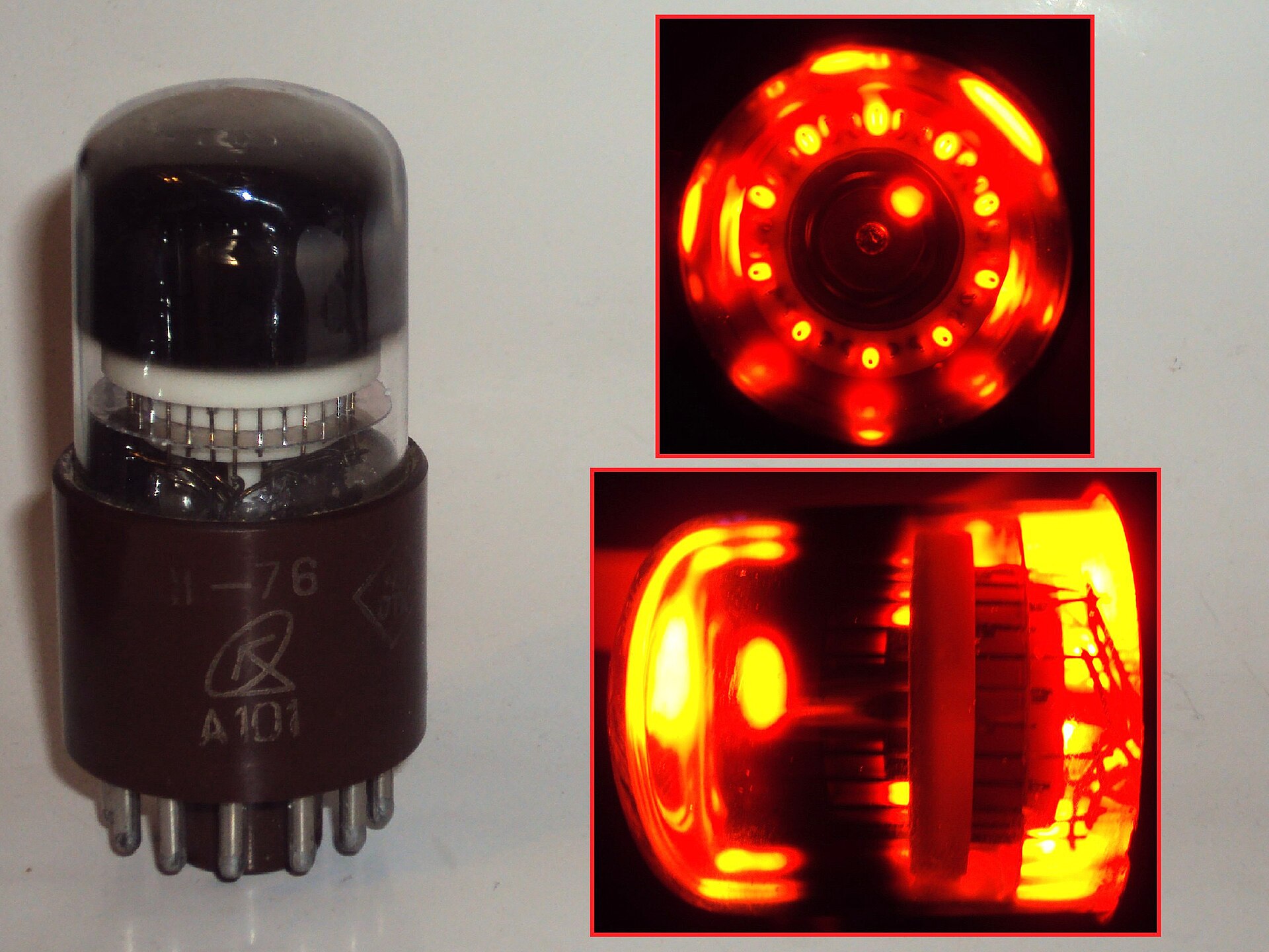
Hold a dekatron up to the light and you see, looking down its axis, a small anode disc in
the dead centre and a ring of ten cathodes spaced evenly around it like the numbers on a
clock face. Between each adjacent pair of main cathodes sit one or two much smaller electrodes —
the guide cathodes (also called transfer or guide electrodes). The whole assembly is a
low-pressure gas discharge, filled with a neon–argon Penning mixture for ordinary counters or
with hydrogen for the fast ones. The anode is held positive through an external anode
resistor; whichever main cathode is negative enough draws the discharge and glows with the same
soft orange (or, in hydrogen tubes, pinkish) light as any neon lamp, because it is the same
physics — the Vs/Vm striking-and-maintaining hysteresis of Vol 2, just packaged as a ten-way
switch.
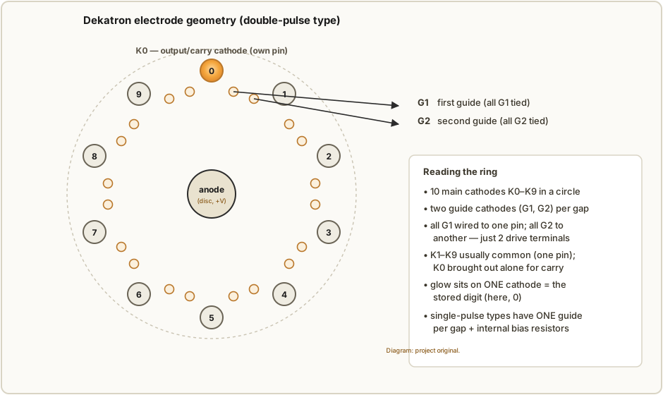
The clever economy is in the wiring. There are ten main cathodes but you do not get ten pins. In a plain counter tube, cathodes K1 through K9 are strapped together inside the envelope and brought out on a single common pin, while the one output cathode K0 gets its own pin so its current can be tapped for the carry. Likewise the guides: every “first” guide in the ring is connected internally to one guide pin (call it G1), and every “second” guide to another (G2). So a double-pulse counter needs only about nine pins — anode, the K1–K9 common, the K0 output, G1, G2, and heater-less housekeeping — to run a full decade. It is a remarkable amount of function per pin. (The selector tubes of §5.4 break this economy on purpose, bringing every cathode out separately, and pay for it with a bigger base.)
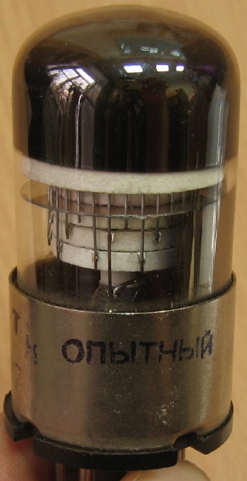
Mechanically the electrodes are pressed-metal vanes and pins on a mica spider, aged and gettered like any quality valve, then given a decimal dial — a printed 0–9 scale — bonded to the face of the envelope so the glowing cathode reads as a number. Some tubes are meant to be read from the top through the dial; others are side-viewed. Either way the reading is direct and needs no decoder: the position of the light is the digit.
5.2 How the glow transfers — the guide pulse
The mechanism is exactly Vol 4’s ring counter, folded into a circle and moved inside the glass. There, an input pulse collapsed the shared anode rail, the lit lamp went dark, and a pre-biased neighbour struck first as the rail recovered, so the glow advanced one stage in a fixed direction. In a dekatron the guides do the pre-biasing, and they do it in sequence so the direction is unambiguous.
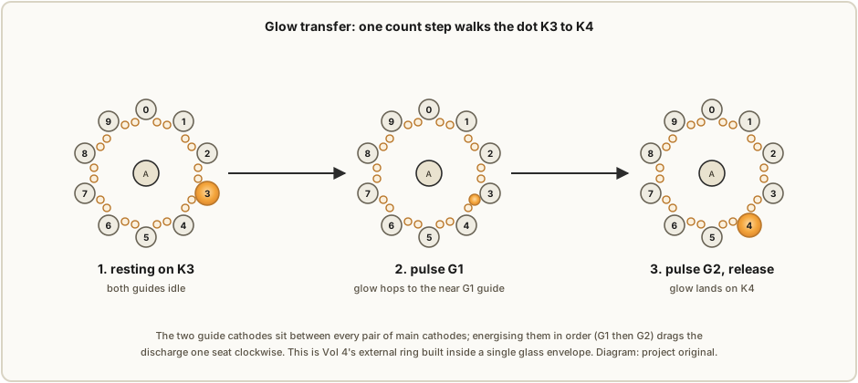
Start with the glow resting on a main cathode — say K3 — with both guides idle and sitting at a modest positive bias so they attract nothing. Now pulse the first guide G1 negative. The guide immediately clockwise of K3 is suddenly the most attractive electrode in the tube, and because the glow is already ionising the gas right next to it, the discharge hops onto that G1 guide almost instantly — priming makes the transfer fast and certain. Next, pulse the second guide G2 (the one a little further clockwise, between the same K3 and the next main cathode K4). The glow steps again, onto G2. Finally, as both guide pulses release, the glow has nowhere to sit except the next main cathode, K4, which is now the nearest cathode still held at the counting bias — so it drops onto K4 and stays there. One input count, one seat clockwise. Because G1 is always energised before G2, the walk is one-directional; reverse the order (G2 then G1) and a bi-directional tube counts down instead.
Two things make this work reliably where a loose ring of surplus neons struggles. First, the
electrodes are matched at the factory and sealed together in one gas fill, so the stage-to-stage
spread in Vs that forces all the binning of Vol 3 is simply absent — every seat in the ring is
the same. Second, the guides sit millimetres from the main cathodes and share the already-ionised
gas, so the transfer is fast and the “pre-bias” is a real, present glow rather than a charge
coaxed onto a coupling capacitor. The dekatron is what a neon ring counter looks like when a tube
engineer, rather than a hobbyist, is allowed to build every part of it to spec.
5.3 The two drive families: double-pulse and single-pulse
Dekatrons come in two flavours distinguished by how many guide sets they have and, therefore, by the waveform you must feed them.
Double-pulse (two-guide) dekatrons have the two guides per gap of Figure 5.1 and need the two-phase drive of §5.2: a pulse on G1, then an offset pulse on G2, for every single count. This is the commonest family — the ETL/Mullard GC10B and GC10/4B, most of the Ericsson counting tubes — and it is the more robust, because the two staggered pulses leave no ambiguity about which way the glow should move. The cost is that you must generate two correctly-timed, correctly-overlapping guide waveforms. In the classic circuit the guides idle at a modest positive bias (pulled up through resistors to a modest rail) and each count drives them negative in turn, pulsing them toward the cathode potential to fire.
Single-pulse dekatrons have only one guide electrode per gap, plus internal biasing resistors (or an asymmetric guide geometry) that make the “wrong” neighbour unattractive so a single pulse on the lone guide advances the glow one seat. The drive is simpler — one line, one pulse per count — which made these tubes attractive where the driving circuit had to be cheap. The trade is that single-pulse tubes are usually unidirectional (they count up only) and can be a little less tolerant, because a single pulse has to do all the steering that two staggered pulses do in the double-pulse tube.
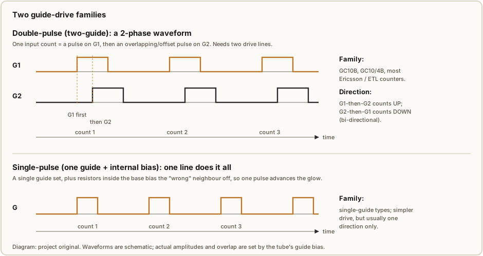
In practice you match the drive to the tube you have. If you are building from a bag of NOS GC10Bs you are building a two-phase pulse shaper; if you have single-pulse tubes you can get away with one transistor and an RC. Either way the pulse amplitude and width are chosen so the glow completes its hop before the pulse releases but the tube has time to deionise between counts — the same recovery-time ceiling that limits every cold-cathode counter, discussed under speed below.
5.4 Counter tubes versus selector tubes
There is a second axis, orthogonal to the drive family: what you intend to do with the count.
A counter dekatron is optimised to be watched or to hand on a carry. Its main cathodes run at modest current — enough for a clean, readable glow — and, as in §5.1, K1–K9 are usually commoned to save pins, with only K0 brought out for the carry tap. The GC10B and the Soviet OG-4 are of this kind. This is the tube you use for a scaler, a frequency divider, or a numbered decade display.
A selector dekatron is built to switch something. Every main cathode is brought out on its own pin — which is why these tubes need a bigger base, thirteen pins or more — so that the position of the glow can close a circuit, latch a relay driver, or select one of ten outputs. Because a selector’s cathode may have to sink useful current into an external load rather than merely glow, selector tubes are specified to run at higher cathode current and their cathodes are built to take it. The Ericsson GS10 family is the classic selector line. You reach for a selector when the count is not the end in itself — when reaching digit 7 must, say, energise the seventh lamp of a display or route a signal — rather than just advance a dial.
Some tubes blur the line (a “counter/selector” with all cathodes out, usable either way), but the distinction to carry in your head is simple: a counter shows or divides, a selector switches, and the selector pays for its extra ability in pins and in current.
5.5 Operating conditions — voltage, current, speed
A dekatron runs on a stiffer, higher rail than the switching-tube rings of Vols 3–4. Typical
anode voltages sit around +400 V, and the useful window runs roughly +400 to +475 V
for inert-gas (neon-filled) counters; the fast hydrogen-filled tubes want more, often
450–600 V. As always the anode is fed through an anode resistor Ra that sets the glow
current on the normal-glow plateau — exactly the Ra = (Vsupply − Vlamp)/Inom relation of Vol 4,
with Vlamp now the tube’s maintaining drop. ⚠ A rail of ~400–475 V DC behind a charged reservoir
capacitor is lethal — treat it with the discipline Vol 14 sets out; do not let the higher
“nice numbered dial” charm of these tubes lull you into forgetting the supply behind them.
Cathode current on the glowing cathode is modest for a counter — typically a few hundred
microamps up to about a milliamp, chosen (via Ra) to give a bright, stable glow without
sputtering the cathode. Selector tubes, sinking current into a load, run higher — up toward
several milliamps, per the specific tube’s rating. The guide electrodes carry only brief pulse
currents.
Speed is set, as everywhere in this series, by deionisation time — the glow needs milliseconds-scale recovery before the next transfer is certain. Ordinary neon-filled counters are happy up to a few kilohertz — the GC10B, for instance, is commonly rated around 4 kHz — and the whole cold-cathode counting family is fairly described as topping out near the ~1 kHz mark for reliable, margin-comfortable operation, with these matched dekatrons doing somewhat better than a hand-binned neon ring. The exception is the hydrogen-filled tubes, whose faster deionisation lets them count into the tens or hundreds of kilohertz, with the very fastest specials quoted up toward ~1 MHz. Those hydrogen tubes were the ones physicists reached for when scaling genuine radioactive-decay pulse rates; for a clock, a divider, or a bench counter, the neon tubes and their few-kHz ceiling are more than enough. If you need to count faster than the tube can transfer, you put a faster pre-scaler (a hydrogen dekatron, or in the transistor era a flip-flop) in front and let the neon tubes handle the slow digits.
5.6 Cascading decades — the carry
One dekatron counts and displays one decimal digit, 0 through 9. To count to 99, or 999, or to divide by 100 or 1000, you cascade decades, and the mechanism is the whole reason K0 gets its own pin. When the glow steps off K9 and lands back on K0 — once every ten input counts — the pulse of cathode current through K0 is tapped off, shaped, and used as the input (the guide drive) to the next tube. The units tube therefore divides the input by ten and its carry clocks the tens tube; the tens tube divides by ten again and clocks the hundreds tube; and so on. A three-tube stack reads a number 000–999 directly off three dials and, tapped at the top, is a clean ÷1000 frequency divider.
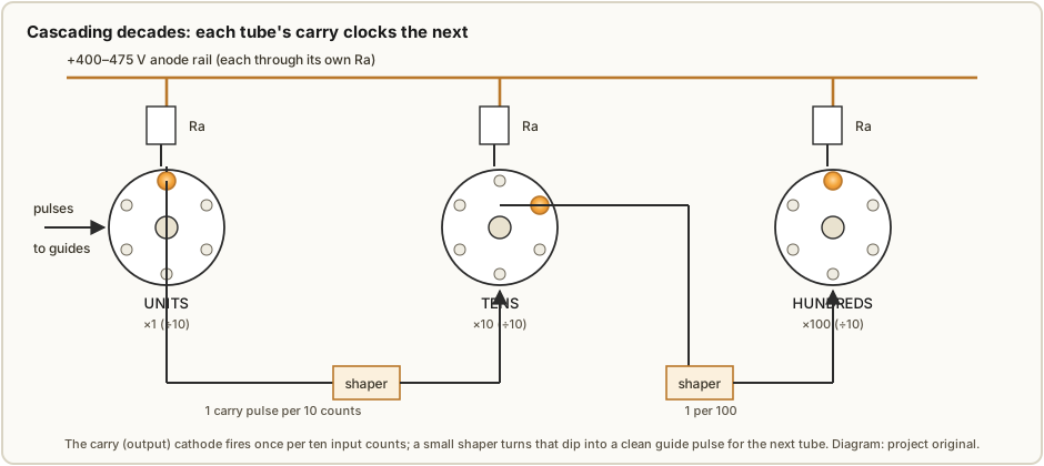
The one part that needs care is the carry shaper. The raw K0 pulse is a brief dip in cathode
current, not a tidy logic edge, and it has to be turned into a guide pulse of the right amplitude
and width for the next tube. In period equipment this was a small neon or a single cold-cathode
trigger tube, or later a transistor; the principle is the same one PA3FWM rediscovered in his neon
clock (Vol 7), where weak modern-lamp carry pulses needed a buffer stage to drive the next
counter reliably. With matched dekatrons the carry is stronger and more repeatable than a bag of
surplus neons will ever give you, but a decade-to-decade shaper is still the piece a first-time
builder most often gets wrong. Note too that a dekatron divides by exactly ten whenever it
transfers reliably — the exact-integer-ratio point Vol 6 makes about all ring counters — so a stack
of N tubes divides by exactly 10^N, adding no frequency error of its own, only whatever jitter and
reliability the tubes’ margins allow.
5.7 The tube families
A working knowledge of a few families covers most of what you will meet on the surplus market. The table below is deliberately hedged where a precise figure depends on the exact variant; consult the specific datasheet (the tube-tester.com and Industrial Alchemy dekatron archives are excellent) before committing to voltages for a given tube.
Table 1 — 5.7 The tube families
| Family / type | Origin | Kind | Drive | Notes |
|---|---|---|---|---|
| GC10B, GC10/4B | ETL / Mullard / Ericsson (England) | Counter (some counter/selector) | Double-pulse | The classic English counting dekatron; neon-filled, ~4 kHz; the tube most hobby dekatron clocks use today |
| GS10 series (e.g. GS10C, GS10C/S = CV2325) | Ericsson (England) | Selector | Double-pulse | Every cathode on its own pin; higher cathode current for switching one-of-ten loads |
| OG-4 (ОГ-4), OA-4 (ОА-4) | Soviet Union | Counter | (per datasheet) | Common, cheap NOS today; the usual choice for a low-cost dekatron project |
| CK6910 | Raytheon (USA) | Counter | Double-pulse | The American entry; less common in Europe but well documented |
| Ericsson counting tubes (Tube Technical Handbook, 1964) | Ericsson (England) | Counter / selector | Double-pulse | The Ericsson handbook is the primary reference for the GC10/GS10 lines |
Two practical notes. First, most of these are NOS-only; like the ZA1002 switching tube of Vol 3 they are no longer made, they vary a little unit to unit, and the cheapest plentiful option today is usually the Soviet OG-4. Second, mind the base and pin-out — counter tubes with a common K1–K9 cannot be used as selectors, and the higher-current selector tubes are wasted (and may be mis-biased) if you only want a dial. Match the tube to the job of §5.4 before you buy a bag of them.

5.8 Where dekatrons were used
For a decade and a half the dekatron was how you counted electronic pulses without a rack of flip-flops. In physics and industry they were the heart of the scaler — the instrument that counted radioactive-decay pulses from a Geiger or scintillation detector, one dekatron per digit, a stack of them reading counts-per-minute straight off their dials. They totted up items on production lines, timed intervals, and divided frequencies in test gear. Any time you see a piece of 1950s–60s laboratory equipment with a row of little round windows each showing a glowing number, you are almost certainly looking at a dekatron scaler.
Two machines lifted the dekatron out of instrumentation and into computing history.
The Harwell WITCH — built at the Atomic Energy Research Establishment at Harwell and originally called the Harwell Dekatron Computer — used dekatrons not merely to count but as memory. It became operational in 1951 and used on the order of 828 dekatrons, storing numbers as the glow position within each tube: a register was a small stack of dekatrons, each holding one decimal digit as a lit cathode, so the machine’s RAM was quite literally rows of glowing dots. It held twenty (later forty) eight-digit decimal registers. It was gloriously slow — a multiplication took between five and ten seconds — but it was patient and reliable, able to run unattended for days, which suited a lab that wanted long unsupervised calculations more than speed. Restored and returned to working order at The National Museum of Computing at Bletchley Park in 2012, it was recognised by Guinness World Records as the oldest working digital computer — and you can still watch its dekatron memory count in glowing gas.
The ANITA calculator — “A New Inspiration To Arithmetic,” built by Bell Punch / Sumlock and launched in 1961 — was the world’s first all-electronic desktop calculator, and its logic and registers were built from cold-cathode tubes, including dekatrons. Where every later calculator went to transistors and then to a single chip, the ANITA did its arithmetic with glow discharge — a full four-function desk calculator whose insides were a forest of neon-orange tubes. It was a commercial success for a few years until transistorised machines undercut it, but it stands as the high-water mark of what cold-cathode counting could do: not just tally pulses, but calculate.
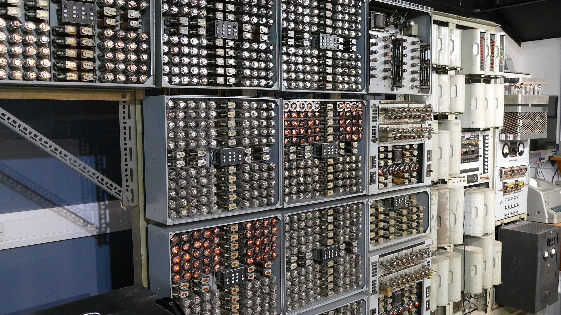
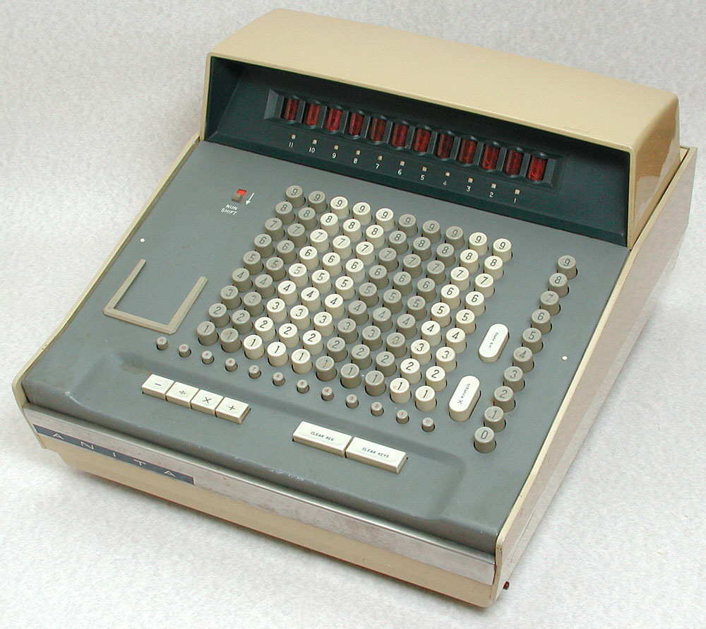
FIGURE SLOT (pending) — A period dekatron scaler (a physics counts-per-minute instrument) with its row of numbered dekatron dials, to ground the “this is what they were actually for” point. Source: a museum or collector photograph.
Set against Vol 4’s fistful of binned surplus neons, the dekatron is the professional’s answer to the same problem — count and divide by ten with glow discharge — and the machines above are what that professionalism bought: instruments, calculators, and one patient, beautiful computer that still counts today. Vol 6 takes up the divider question the cascade of §5.6 raises — just how accurate is division by a ring, dekatron or otherwise — and Vol 12’s gallery returns to the WITCH, the ANITA, and the scalers with room for more of the photographs these tubes so richly deserve.
References
- J. B. Dance, Electronic Counting Circuits (London: Iliffe Books / New York: American Elsevier, 1967) — the canonical treatment of cold-cathode counting tubes and dekatrons; in the site’s reference library.
- Ericsson Telephones Ltd, Tube Technical Handbook (1964) — GC10 / GS10 dekatron data — https://frank.pocnet.net/other/Ericsson/EriccsonTelephonesLimited_TubeTechnicalHandbook_1964.pdf
- Dekatron datasheet archive (GC10B, GC10/4B, GS10C, CK6910, OG-4) — tube-tester.com nixie/dekatron section; Industrial Alchemy “Dekatron Glow Transfer Counting Tubes” — https://www.industrialalchemy.org/tubepage.php?item=15
- “Cold-Cathode Tube & Dekatron” and “The Technology Explained” — vintagecalculators.com and anita-calculators.info (ANITA dekatron/cold-cathode logic).
- “Dekatron,” Wikipedia — electrode structure, gas fills, speed, families — https://en.wikipedia.org/wiki/Dekatron
- “Harwell computer” (Harwell WITCH / Harwell Dekatron), Wikipedia, and The National Museum of Computing — dekatron memory, 828 tubes, 1951 operation, 2012 restoration — https://en.wikipedia.org/wiki/Harwell_computer
- R. Dekker, “A Neon Ring Counter” — the external-ring mechanism the dekatron internalises — https://www.dos4ever.com/ring/ring.html
Comments (0)