Neon Ring Counters · Volume 4
The Ring Counter — Theory of Operation
The common-anode topology, the glow-transfer mechanism pulse by pulse, and every design equation with its units
This is the volume the whole series has been circling. Vol 2 established that a neon
lamp has memory — it strikes at one voltage Vs and only lets go at a much lower one
Vm, so between those two it stays in whichever state you last put it — and Vol 3 sorted
out which lamps have a wide enough Vs−Vm window to be trusted. Now we wire a handful of
those bistable lamps into a single circuit and make the memory move: one lamp lit, the
rest dark, and every input pulse walking the lit spot one place along, always in the same
direction, forever. Nothing in the count path switches but the gas itself. There is no
flip-flop, no clock gating, no steering logic in the modern sense — just a shared
high-voltage rail, one resistor per lamp, and a small capacitor between neighbours, all
arranged so that when you knock the lit lamp out, the next lamp around the ring is the
one best placed to light. Get the three component values right and the thing counts like a
Swiss movement; get them wrong by a few kilohms and it stalls, doubles, or runs backwards.
This volume is about getting them right — the topology, the mechanism traced pulse by
pulse, and the design mathematics that Ronald Dekker distilled from J. B. Dance’s 1967
treatment and that Luc Small then proved on a benchful of surplus Soviet lamps.
⚠ Everything here lives on a rail between roughly 150 V and 250 V DC sitting behind a charged reservoir capacitor. That is lethal, silent, and does not trip anything. Prove every rail discharged with a meter before you touch it; the full discipline is Vol 14.
4.1 The common-anode topology
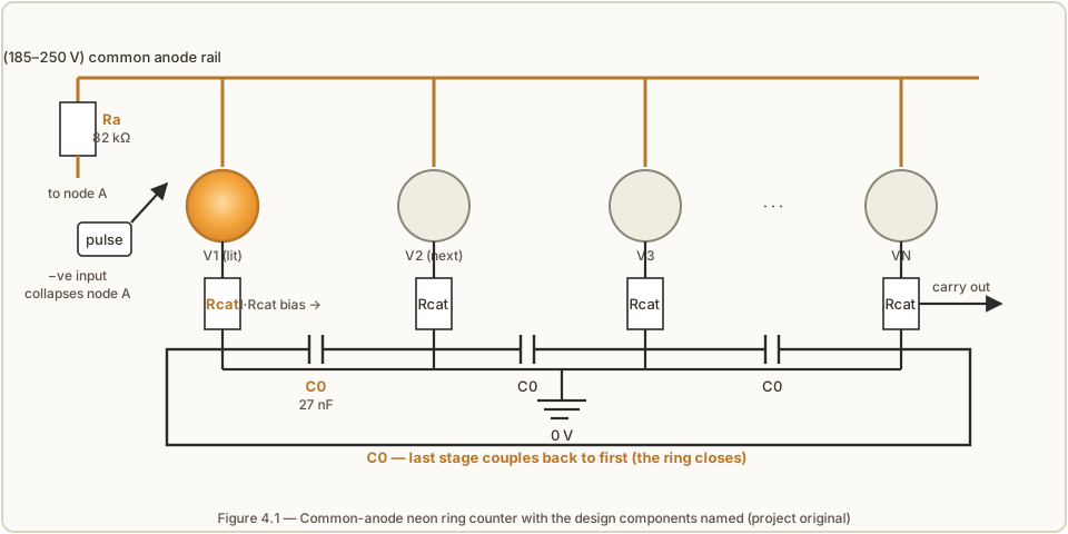
Strip the ring to its skeleton and it is astonishingly sparse. Every lamp in the ring
shares one common anode node, fed from the high-voltage supply through a single
anode resistor Ra. Each lamp then has its own cathode resistor Rcat to ground,
and — the one non-obvious part — each lamp’s cathode is tied to the next lamp’s cathode
through a small coupling capacitor C0. The last stage couples back to the first, so
the chain closes into a literal ring. That is the entire circuit: N identical lamps,
N cathode resistors, N coupling capacitors, and one shared anode resistor. Figure 4.1
names every part.
The shared anode is what makes the ring both cheap and clever. Because all the lamps hang
off one node, a single input pulse applied there acts on all of them at once — it does
not need to be routed to a particular stage, which would demand exactly the decoding logic
the ring is supposed to do without. The pulse simply says “everyone off,” and the network
of cathode resistors and coupling capacitors decides, on its own, who comes back on. The
anode resistor Ra does two jobs: in the steady state it sets the lamp current on the
normal-glow plateau (Vol 2’s V–I curve), and during a pulse it is the resistor through
which the anode node recharges, so together with C0 it sets how fast the node recovers.
The cathode resistor Rcat is where the real trick lives, because the small voltage it
develops when its lamp is lit is the entire steering mechanism, as the next section shows.
A note on where the input pulse goes. In the classic Dance/Dekker form the negative pulse
is injected onto the common anode node, pulling it down. In practice a modern builder more
often pulls the node down actively — Luc Small does exactly this with a high-voltage NPN
transistor (an MPSA42) whose collector sits on the anode node and whose base is driven
by a 555 timer, and the “coupling capacitor” across that transistor is his 100 nF part.
The two views are electrically the same event seen from opposite ends: the anode node must
briefly fall below Vm so that whatever lamp is lit can no longer sustain its discharge.
How it is made to fall — a capacitively-coupled pulse, a transistor pull-down, a
gas-trigger tube — is a drive-circuit choice (Vol 13), not part of the ring’s own theory.
4.2 The transfer bias — what one lit lamp does to its neighbour
Here is the single idea the entire ring rests on. When a lamp is lit, its cathode current
I flows through that lamp’s cathode resistor Rcat, and by Ohm’s law it lifts the
lamp’s cathode above ground by a voltage
Vcat = I · Rcat (volts, with I in amperes and Rcat in ohms).
Dekker calls this the cathode transfer bias. It is a small voltage — a handful of
volts to a few tens of volts — but it is the flag that marks “I am the lit one,” and,
crucially, it gets shared with the next lamp’s cathode through the coupling capacitor.
Because a capacitor holds whatever charge is put across it, C0 copies a version of the
lit lamp’s raised cathode potential onto the neighbour’s cathode. While everything sits
steady this does nothing visible — the neighbour is still dark, its anode-to-cathode
voltage still below Vs. But it has quietly pre-charged the geometry so that the instant
the anode node is knocked down and then allowed to recover, the pre-biased neighbour is the
one lamp in the ring whose anode-to-cathode voltage climbs fastest toward its own Vs.
Think of it as a footrace where every runner starts on the same gun (the anode recovering)
but the neighbour of the lit lamp gets a head start measured out precisely by I · Rcat.
If that head start is chosen well, the neighbour always reaches the striking line first,
lights, and — because it is now the lit lamp — develops the transfer bias on its own
cathode resistor, handing the head start one stage further along. The lit spot has moved.
Everything that follows in this volume is really just quantifying “chosen well”: how big
the head start must be to beat the manufacturing spread between lamps, and how small it
must stay so that it never lights an idle lamp all by itself.
4.3 The glow transfer, pulse by pulse
Let us trace one full transfer in slow motion. Call the lit lamp V1 and its downstream
neighbour V2, and follow the anode node and the two cathodes through four instants.
Figure 4.2 draws the same sequence.
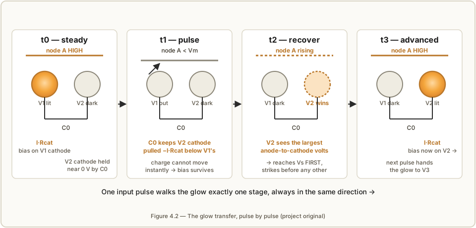
t0 — steady state. V1 glows. Its current I flows through its Rcat, raising V1’s
cathode to I · Rcat above ground. Through the coupling capacitor C0, that raised
potential appears (minus the capacitor’s own steady drop) at V2’s cathode too — so the
capacitor is charged to the difference between the two cathode potentials. V2 is dark:
the anode node is high, but V2’s anode-to-cathode voltage is below its striking voltage,
so it waits.
t1 — the input pulse. A negative pulse (or a transistor pull-down) drags the common
anode node below Vm. V1 can no longer sustain its discharge and extinguishes. Its
cathode current stops, so the I · Rcat bias on V1’s own cathode would like to collapse
to zero — but it cannot do so instantly, because C0 is in the way. A capacitor’s voltage
cannot change in zero time; the charge stored across C0 at t0 is still there at t1. The
result is that for the crucial moment right after the pulse, C0 holds V2’s cathode
pulled down relative to V1’s by that stored I · Rcat. The memory of “who was lit” has
been transferred from a glowing gas (which has just gone out) into a charged capacitor
(which has not).
t2 — recovery. The pulse ends and the anode node begins to climb again, recharging
through Ra (and shaped by C0). Every lamp in the ring now sees a rising anode, but they
do not see the same anode-to-cathode voltage, because their cathodes are not at the
same potential. V2’s cathode is still held low by the charge on C0, so V2 sees the
largest anode-to-cathode voltage of any lamp in the ring. It therefore reaches its
striking voltage Vs first — before V1 can re-ignite, and before any more distant
lamp gets close. V2 strikes.
t3 — advanced. V2 is now the lit lamp. Its current flows through its Rcat,
developing the transfer bias on V2’s cathode, which C0 copies onto V3. V1’s cathode
capacitor, no longer fed, has relaxed back to rest. The ring is in exactly the same
configuration it was at t0, shifted one stage clockwise. Feed it another pulse and the glow
steps to V3; feed it N pulses and it has gone once around and lit V1 again — and on
that wrap it can hand a carry pulse to the next ring (Section 4.8).
The beauty of it is that the same three components do all four jobs. Rcat is the sensor
(it measures which lamp is lit, as a voltage). C0 is the memory (it carries that
measurement across the dark instant when no lamp is lit). And the lamp’s own Vs/Vm
hysteresis is the decision (whichever lamp reaches Vs first wins, and having won, holds
until the next pulse). There is no separate logic anywhere.
4.4 Why it only goes one way
A fair question at this point: if C0 couples V1’s cathode to V2, and every stage is
identical, why does the glow not step backwards to V0 just as happily as forwards to
V2? The answer is the deliberate asymmetry built into how the coupling capacitors are
wired. Each C0 links a lamp’s cathode to one neighbour — the downstream one — so the
pre-bias only ever appears on the stage in the forward direction. V0 (the upstream
neighbour) is coupled to its downstream side, which is V1; when V1 was lit, V0
received no head start from it, because the coupling runs V1 → V2, not V1 → V0. The
capacitors are directional plumbing: charge from a lit lamp is offered to exactly one
successor, and the ring inherits that one-wayness.
This is worth dwelling on because it is where a ring counter differs from a mere chain of
bistables. The hysteresis of the lamps gives you memory and the shared anode gives you
a common reset, but neither of those alone has a preferred direction. Directionality is
manufactured entirely by the coupling topology — by the fact that C0 reaches forward and
not back. Break that asymmetry and the ring loses its mind: if stray capacitance or a
wiring error couples a cathode to its upstream neighbour as strongly as to its
downstream one, the glow can hop either way and the count becomes meaningless. Bidirectional
(up/down) counters exist and are genuinely useful, but they achieve reversibility by
providing two steering paths and choosing between them with the drive — they do not get
it by accident. For the plain forward ring of this volume, the rule is simple: every C0
points the same way around the circle, and that is the arrow the glow follows.
There is a second, subtler reason the forward stage wins that is worth naming. At the
instant of recovery the just-extinguished lamp V1 is the least likely of all to
re-strike, because it has just been through deionisation — its gas is still partly ionised
and its local conditions are disturbed, and more importantly the collapse of its own
cathode bias momentarily raises its cathode, reducing its anode-to-cathode voltage. So the
race at t2 is really between V2 (pre-biased, primed to win) and the more distant idle
lamps (unbiased), with V1 handicapped. That triple ordering — biased neighbour first,
idle lamps second, spent lamp last — is what makes a well-designed ring advance by exactly
one stage and never rattle.
4.5 The design equations
Everything above is qualitative; now we make it numeric. The whole design reduces to
choosing three component values — Rcat, Ra, and C0 — and the governing quantity is
the transfer bias I · Rcat. It must be large enough to guarantee the pre-biased lamp
wins the race despite the spread in striking voltages between real lamps, and small
enough that it never, on its own, lights an idle lamp. Those two requirements are the two
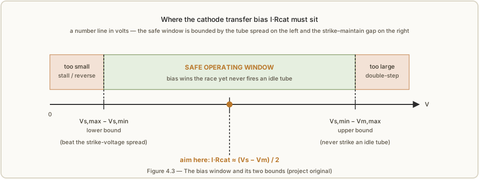
bounds, and the ideal design sits squarely between them. Figure 4.3 draws the window.
4.5.1 The two bounds
Define the symbols first, because the bounds are all about worst-case combinations of lamp-to-lamp spread:
I— the chosen (nominal) lamp current, in amperes. Also writtenInom.Rcat— the cathode resistor, in ohms.Vs,min,Vs,max— the lowest and highest striking voltage across your batch of lamps, in volts.Vm,min,Vm,max— the lowest and highest maintaining voltage across the batch, in volts.
Upper bound — do not fire an idle lamp. The transfer bias raises a lamp’s cathode,
which is the same as lowering the anode-to-cathode voltage that lamp needs the rail to
supply before it strikes. If the bias is too large, an idle lamp that happens to have the
lowest striking voltage in the batch (Vs,min) could be pushed over the edge by nothing
more than the steady anode sitting a hair above the highest maintaining voltage (Vm,max).
To be safe against that worst pairing:
I · Rcat < Vs,min − Vm,max.
Lower bound — win the race against spread. At recovery the pre-biased lamp must reach
Vs before an unbiased lamp does, and the unbiased lamps are not identical — their
striking voltages are spread from Vs,min to Vs,max. The head start I · Rcat must be
big enough to overcome the worst case, where the pre-biased lamp happens to be a
high-Vs one (Vs,max) racing an idle low-Vs one (Vs,min):
I · Rcat > Vs,max − Vs,min.
Read the two together and the message is stark: the safe window for I · Rcat is only as
wide as the strike–maintain gap minus the strike-voltage spread. This is exactly why Vol 3
made such a fuss about binning — every volt of spread you can squeeze out of Vs,max − Vs,min is a volt you get back in operating margin, and cheap indicator neons with their
~12–20 V window and wild unit-to-unit scatter can leave almost no window at all. A batch of
purpose-built switching tubes with a ~60 V window (the Philips ZA1002 of Vol 3) makes both
inequalities trivial to satisfy; a bag of unbinned NE-2s can make them impossible.
4.5.2 The ideal centre and the cathode resistor
With the window defined, the safest place to sit is the middle of it. When the lamps are reasonably matched the two bounds are roughly symmetric about the point where the bias equals half the strike–maintain gap, so Dekker’s rule of thumb is to aim for
I · Rcat ≈ (Vs − Vm) / 2,
using the batch-average Vs and Vm. Solving for the resistor with I = Inom gives the
working formula for the cathode resistor:
Rcat = (Vs,avg − Vm,avg) / (2 · Inom) (ohms, with voltages in V and Inom in A).
Two worked instances anchor this. Luc Small’s lower cluster of burned-in IN-3 lamps
measured Vs 73–77 V and Vm 38–42 V (so Vs,avg ≈ 75 V, Vm,avg ≈ 40 V), and he chose
Inom = 800 µA. The centre formula gives Rcat = (75 − 40) / (2 · 800 µA) ≈ 21.9 kΩ. In
practice Luc used a slightly lower value — about 18 kΩ (his own more conservative
form of the formula, which deliberately pushes the bias below dead-centre to respect the
tight upper bound, computed 16 875 Ω and rounded up). That is a legitimate design
choice: with a narrow window you bias toward the “never false-strike” side, accepting a
smaller head start because the strike spread within a well-binned cluster is small.
Dekker’s ten-stage ring, running cheap “drop-shaped” neon lamps he measured at a
usefully wide window (Vs ≈ 97.5 V, Vm ≈ 68.6 V, a ≈29 V gap — wider and far more
consistent than typical indicator neons), landed on Rcat = 12 kΩ — comfortably above the ~7 kΩ its
centre formula suggests, buying extra head start on the lower (sequencing) bound because
his generous window left plenty of room before the upper bound. The lesson is that the
formula gives you the centre of the target; how far off-centre you deliberately aim depends
on whether your batch’s spread or its false-strike risk is the thing you fear more.
4.5.3 The anode resistor
The anode resistor sets the lamp current on the normal-glow plateau. In the steady state,
the supply voltage is dropped across three things in series: Ra itself, the lamp’s own
maintaining drop (≈ Vm, which the normal glow holds nearly constant), and the cathode
resistor Rcat. The simplest form ignores the small cathode-resistor drop and treats the
lamp as a fixed Vlamp ≈ Vm:
Ra = (Vsupply − Vlamp) / Inom (ohms).
For a tighter value, subtract the cathode-resistor drop as well, since that voltage is also in the series path:
Ra = (Vsupply − Vm,avg − Inom · Rcat) / Inom.
This exact form is what Luc used: Ra = (150 V − 40 V − 800 µA · 16 875 Ω) / 800 µA = (150 − 40 − 13.5) / 800 µA = 96.5 V / 800 µA ≈ 120 625 Ω, rounded to 120 kΩ. Note how
much the Inom · Rcat term matters here — 13.5 V out of a 150 V rail — so on a low-voltage
build the simpler formula (which would give ≈ 137 kΩ) is meaningfully off and the exact
form is worth using. Dekker, on his higher rail, used Ra = 82 kΩ.
A subtlety worth flagging: on the common-anode ring, a single shared Ra feeds whichever
one lamp is lit, so Ra sees only one lamp’s current at a time, and the formula above is
correct as written. If you instead give every lamp its own anode resistor (a variant), each
resistor is sized the same way but the shared-node behaviour during a pulse changes; this
volume assumes the shared-Ra topology of Figure 4.1 throughout.
4.6 Sizing the coupling capacitor C0
If Rcat sets how much head start the next lamp gets, C0 sets how long that head start
survives and how fast the anode recovers — and it is the component most likely to be
wrong on a first build. Its value is a genuine trade-off with a failure mode at each
extreme, sketched in Figure 4.4.
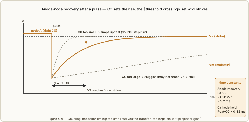
There are really two time constants in play, and it helps to keep them separate. The
cathode-hold time constant, Rcat · C0, sets how long C0 can keep the next lamp’s
cathode pulled down after the lit lamp goes out — this is the memory that must outlast the
dark instant. For Dekker’s values, Rcat · C0 = 12 kΩ · 27 nF ≈ 0.32 ms. The
anode-recovery time constant, Ra · C0, sets how quickly the anode node climbs back
toward the rail — this is what shapes the race in Figure 4.4. For Dekker, Ra · C0 = 82 kΩ · 27 nF ≈ 2.2 ms. Both scale with C0, which is why one component controls the whole
transfer.
Too small a C0 and two things go wrong: the cathode-hold constant becomes so short
that the pre-bias has bled away before the anode recovers (no head start → the transfer can
fail entirely, exactly Dekker’s warning that “without C0 the circuit would not function at
all”), and the anode node snaps back up so fast that the just-extinguished lamp — or the
one two stages along — can catch a strike too, advancing the glow by two on a single pulse.
That second failure is double-stepping, and it is the classic symptom of a
too-fast recovery.
Too large a C0 and the anode node recovers so sluggishly that it may not climb back
to Vs within the time the drive allows before the next pulse — the pre-biased lamp never
quite strikes and the ring stalls, dropping counts. An over-large C0 also slows the
maximum counting rate directly, since each transfer now takes several milliseconds.
The practical target, then, is a C0 whose Ra · C0 recovery is a couple of milliseconds
— slow enough to guarantee one-at-a-time striking, fast enough to keep up with the intended
count rate. Dekker’s 27 nF and Luc’s 100 nF bracket the useful range for
rails around 150–250 V; the exact value is best trimmed on the bench, watching for the
double-step (reduce nothing — increase C0) or the stall (decrease C0). Vol 10 covers
which 27–100 nF capacitor to buy: low leakage and low dielectric absorption matter here
because C0 is holding a small bias precisely, so polypropylene or C0G/NP0 is preferred
and electrolytics and high-K ceramics are firmly out.
4.7 Dekker’s worked ten-stage ring
It is worth collecting the canonical worked values in one place, because they are the
reference every other neon-ring build measures itself against. Dekker built a ten-stage
ring (a decade — feed it ten pulses and the glow returns to the start) using inexpensive
“drop-shaped” cold-cathode neon lamps (not the Philips ZA1002 switching tubes, which he
tried in a separate experiment that decayed-tritium priming spoiled — see Vol 3), and
settled on the values below. (The Vs ≈ 140 V / Vm ≈ 100 V pairing that appears in
Dekker’s write-up is his deliberately fictitious teaching example for the hysteresis maths,
not the tubes in the physical ring.)
Table 1 — 4.7 Dekker's worked ten-stage ring
| Symbol | Value | What it is |
|---|---|---|
N | 10 stages | ring length → divides by 10 |
Vsupply | 185–250 V | usable rail range |
Vs (tube) | ≈ 97.5 V | striking voltage of the drop-shaped neons (measured 93.7–101.4 V) |
Vm (tube) | ≈ 68.6 V | maintaining voltage → ≈ 29 V window (measured 66.4–72.0 V) |
Rcat | 12 kΩ | cathode resistor (centre formula ≈ 7 kΩ; biased high for margin) |
Ra | 82 kΩ | shared anode resistor |
C0 | 27 nF | coupling / recovery capacitor |
Rcat · C0 | ≈ 0.32 ms | cathode-hold time constant |
Ra · C0 | ≈ 2.2 ms | anode-recovery time constant |
The 185–250 V figure is not a tolerance — it is the operating map. Below about 185 V
the rail cannot reliably lift the anode node to Vs after a pulse and the counter skips
(stalls, drops counts). Above about 250 V the recovery is so vigorous that the ring
double-steps, counting at twice the clock rate. Between those limits it counts cleanly,
and the width of that window — a full 65 V — is a direct dividend of using wide-window
tubes and centring the bias. A ring built from marginal indicator neons has a far narrower
supply window, which is why Luc’s IN-3 build wants a stiff, regulated 150 V rail (Vol 7,
Vol 8): a few volts of supply sag on a narrow-window ring is the difference between counting
and stalling.
On speed: a purely capacitively-coupled cold-cathode ring is limited by the lamps’ deionisation (recovery) time of a few milliseconds, so it tops out around ~1 kHz. Dekker reached far higher — around 500 kHz — but only by abandoning gentle capacitive coupling for hard TTL-level pulses driving a high-voltage transistor that yanks the anode node down fast, at roughly a 10 % duty cycle. That is a different, actively-driven animal; the passive ring of Figure 4.1 is a sub-kilohertz device and is happiest counting things a human can watch (Vol 6 returns to what this speed ceiling means for frequency division).
4.8 Ring length, divide ratio, and the carry tap
The ring’s most useful property falls straight out of its geometry: a ring of N stages
produces one output event for every N input pulses, so it divides the input frequency
by exactly N. Ten stages divide by ten; six stages divide by six; two stages divide by
two (an octave, which is precisely how the Philicorda organ of Vol 6 makes its lower notes).
The division ratio is a counted integer, not an analogue approximation — provided the ring
counts reliably, it is exactly N, with no ratio error of its own. That subtlety, and the
difference between a true counting divider and a fussier injection-locked one, is the whole
subject of Vol 6; here it is enough to know that you set the divide ratio simply by choosing
how many lamps to put in the ring.
To use the division you need a carry (or output) pulse — a signal that fires once per
revolution to clock the next ring in a chain. You get it by tapping one chosen cathode.
Every time the glow lands on that stage, its cathode jumps up by I · Rcat; every time the
glow leaves, it drops back. So the tapped cathode produces one clean voltage pulse per N
input pulses — exactly the carry you want. Route it (through a coupling capacitor, and in
the PA3FWM clock through a buffer lamp that re-amplifies the weak pulse, Vol 7) to the
input of the next decade, and you have cascaded division: two rings of ten give ÷100, a ÷10
then a ÷6 give the ÷60 a clock’s seconds-to-minutes stage needs, and so on. The PA3FWM neon
clock chains eight such rings — dividers of ÷10, ÷5, ÷10, ÷6 to get from 50 Hz mains down to
once-per-minute, then time counters of ÷10, ÷6, ÷10, ÷3 for the minutes and hours digits —
and every one of those taps is a single cathode watched for its once-per-revolution pulse.
Which cathode you tap does not change the ratio (it is always N); it only sets the phase
of the carry, so you pick the stage that gives the cleanest edge and the right timing
relative to the display.
4.9 The Manley–Buckley origin, and how capacitive coupling improved on it
The neon ring counter did not begin with the elegant three-component circuit above. The canonical first appearance is Manley and Buckley’s “Neon Ring Counter” in Electronics, January 1950 — a three-decade counter that steered the glow not with coupling capacitors but with germanium point-contact diodes. In that scheme each stage’s cathode is connected to the next through a diode that conducts in only one direction, so when a lamp is knocked out the diode network offers the transfer charge a one-way path to the successor stage. The diodes are the directionality: they are the asymmetry, made explicit as a component rather than as a wiring convention. Manley and Buckley’s design could count, decrement, reset and preset, and reached impressively high rates (tens of thousands of pulses per second) because the diode steering did not rely on a slow capacitor recovery.
Dekker’s (and Dance’s) capacitively-coupled ring is the descendant that traded some of
that complexity away. Replacing the steering diode with a plain coupling capacitor C0 does
two nice things. First, it removes an active, era-specific, and then-expensive part — early
germanium diodes were finicky and drifty — leaving a circuit of nothing but lamps, resistors
and capacitors that will outlive any semiconductor in the box. Second, it unifies the
memory and the steering into one component: the same capacitor that carries the pre-bias
forward (steering) is the one that holds it across the dark instant (memory), whereas the
diode version needs the capacitor for memory and the diode for direction. The price is
speed and a fussier timing window — the passive ring’s few-millisecond recovery is exactly
the C0 trade-off of Section 4.6 — which is why the purely-capacitive ring is a
sub-kilohertz device where the diode-steered original could run faster. For a hobbyist ring
you want to watch count, or an organ divider working at audio rates, the capacitive version’s
simplicity and longevity win handily; the diode heritage is why you will still see
one-way-steering diodes in the bidirectional and high-speed variants.
4.10 Failure modes, read straight off the equations
The satisfying thing about the design mathematics is that every way a ring can misbehave maps to a specific inequality it has violated. When a bench ring plays up, do not guess — read the symptom back to the bound.
-
Double-stepping (counts two per pulse). The glow jumps two stages at once, or the count runs at twice the clock. Cause: the anode node recovers too fast, so a second lamp catches a strike before things settle — the upper bound
I · Rcat < Vs,min − Vm,maxis being violated (bias too large), orC0is too small (recovery too fast), or the rail is too high (Dekker’s “>250 V” case). Fixes, in order: raiseC0, lower the supply toward the middle of its window, or reduceRcatto shrink the bias. -
Stalling / skipping (drops counts, or stops). The glow fails to advance and either sits still or dies out. Cause: the pre-biased lamp never reaches
Vsin time — the lower boundI · Rcat > Vs,max − Vs,minis being violated (bias too small to beat the batch spread), orC0is too large (recovery too sluggish), or the rail has sagged below its usable floor (Dekker’s “<185 V” case). Fixes: bin the lamps harder to shrinkVs,max − Vs,min, raiseRcata little, lowerC0, or stiffen and raise the supply. -
Running backwards / erratic direction. The glow steps the wrong way, or hops unpredictably. Cause: the forward asymmetry of Section 4.4 has been compromised — a wiring error, stray capacitance coupling a cathode to its upstream neighbour, or lamps so badly mismatched that spread swamps the deliberate
I · Rcathead start. Fixes: check theC0orientation around the ring, keep cathode wiring short and separated, and re-bin. -
Won’t transfer at all. No stepping; the lit lamp just stays lit or the whole ring goes dark on a pulse. Cause:
C0far too small (or missing) so there is no memory across the dark instant, or the pulse fails to pull the anode belowVmso nothing extinguishes. Fixes: confirmC0is present and of the right order, and confirm the pulse depth actually drops the node below the highestVmin the batch.
Every one of those is a margin problem, and every margin in the ring traces back to the
same two levers: the tube spread (Vs,max − Vs,min and Vm,max − Vm,min, shrunk by
binning and burn-in, Vols 3 and 11) and the supply stability (which moves the whole
operating point, stiffened by a regulated rail, Vols 8 and 9). The passive network in
between — Ra, Rcat, C0 — only decides where in that margin you sit. Set it by the
equations of Section 4.5, trim C0 on the bench by Section 4.6, and the ring will count as
reliably as its tubes allow, which is the honest limit that runs through this whole series.
References
- R. Dekker, “A Neon Ring Counter” / Ring Counter Variations — https://www.dos4ever.com/ring/ring.html (the design equations, the cathode-transfer-bias analysis, the 10-stage worked values, and the speed limits).
- L. Small, “Neon Ring Counters” (2016) — https://lucsmall.com/2016/10/08/neon-ring-counters/ (the modern IN-3 build:
Rcat/Raformulas, 150 V / 800 µA / 18 kΩ / 120 kΩ / 100 nF, and the 555 + MPSA42 pulser). - P.-T. de Boer (PA3FWM), “A clock using neon lamps as logic elements” — https://www.pa3fwm.nl/projects/neonclock/ (cascading eight rings, the carry tap, and the buffer-lamp fix).
- J. B. Dance, Electronic Counting Circuits (London: Iliffe Books / New York: American Elsevier, 1967) — in the site’s reference library (the canonical cold-cathode-counting treatment underlying all of the above).
- Manley & Buckley, “Neon Ring Counter,” Electronics, January 1950 (the original diode-steered ring counter).
Comments (0)