Neon Ring Counters · Volume 15
Cheatsheet & Glossary
The whole series distilled onto one laminate-ready card — tube data, design equations, the six-step recipe, safety rules, and a glossary
This final volume is the card you keep on the bench, not the book you read in a chair. Everything below has been argued out at length in Vols 2 through 14; here it is boiled down to tables, formulae, and lists you can scan while a probe is in one hand and a bag of surplus neons is in the other. Nothing here is new — if a number surprises you, the volume that derives it is named in prose so you can go back and check the reasoning. Treat this as an index with the arithmetic pre-chewed: the tube you can trust and the tube you must sort, the five resistor-and-capacitor relations that turn a row of lamps into a counter, the relaxation formula that got you started, the six steps that get you to a working ring, and the handful of safety rules that keep the whole exercise from becoming your last one. Print it, laminate it, and keep the ⚠ line in §15.9 where you can see it.
15.1 Tube quick-select
The single number that decides how hard a build will be is the hysteresis window Vs − Vm
(striking minus maintaining voltage). Wide is forgiving; narrow must be binned. This table
matches Vol 3; the switching-tube figures and the tritium half-life match Vol 2 as well.
Table 1 — 15.1 Tube quick-select
| Tube | Vs (strike) | Vm (maintain) | Vs − Vm window | Priming | Availability |
|---|---|---|---|---|---|
| Barium-cathode indicator neon (NE-2 / IN-3) | ~65–110 V (nom. ~90 V) | ~55–60 V | ~12–20 V — marginal | Photo-sensitive; suffers the dark effect | Cheap, plentiful; must be binned |
| Philips ZA1002 switching tube | ~170 V (169.1–171.0 V measured) | ~105 V (104.8–105.2 V) | ~60 V — luxurious | Tritium primed, <1 ms strike (t½ = 12.3 y) | NOS-only; aged stock strikes erratically 170–220 V |
| Philips ZA1001 switching tube | (same family; the Philicorda octave-divider tube) | — | large | as ZA1002 family | NOS-only; see sibling ../Philicorda/ |
| Dekatron (integrated 10-stage ring) | — | — | n/a (one envelope) | some types include a priming cathode | NOS; see §15.8 and Vol 5 |
Notes that never change: ~99.99 % of commercial neons are the NE-2/IN-3 barium-cathode type,
so binning is nearly always mandatory. The ZA1002’s tritium priming has decayed through roughly
five half-lives on any 1960s tube, leaving only 1/32 to 1/64 of the original — Dekker saw
exactly this erratic striking. A dekatron’s anode runs far higher than any of the above:
**+400–475 V** (see §15.8).
Luc Small’s three measured IN-3 clusters (the worked example throughout, from Vol 3) after a 48-hour burn-in:
Table 2 — 48-hour burn-in
| Cluster | Count | Vs | Vm |
|---|---|---|---|
| Lower | 14 | 73–77 V | 38–42 V |
| Middle | 8 | 82–86 V | 42–46 V |
| Upper | 11 | 88–92 V | 48–53 V |
15.2 The ring design equations, all in one place
These are the whole of Vol 4’s design mathematics on one card. Define the symbols once:
Vs, Vm are a stage’s striking and maintaining voltages (subscript min/max/avg over
the binned cluster); I is the lit-stage cathode current and Inom the value you design for
(A); Rcat the per-stage cathode resistor (Ω); Ra the common anode resistor (Ω); C0 the
inter-stage coupling capacitor (F); Vsupply the rail (V); Vlamp ≈ Vm the lit lamp’s
maintaining drop (V); N the number of stages.
Table 3 — 15.2 The ring design equations, all in one place
| Quantity | Relation | Purpose |
|---|---|---|
| Transfer-bias lower bound | I·Rcat < Vs,min − Vm,max | No stray/false strikes of a resting stage |
| Transfer-bias upper bound | I·Rcat > Vs,max − Vs,min | Sequencing wins over tube-to-tube spread |
| Ideal centre | I·Rcat ≈ (Vs − Vm) / 2 | Bias parked mid-window for maximum margin |
| Cathode resistor | Rcat = (Vs,avg − Vm,avg) / (2·Inom) | The value you actually fit |
| Anode resistor | Ra = (Vsupply − Vlamp) / Inom (Vlamp ≈ Vm) | Sets the stage current on the glow plateau |
| Coupling cap | C0 sets transfer rise-time | Too small → no transfer; too large → double-stepping |
| Divide ratio | ratio = N (ring length) | One carry pulse out per N input pulses |
Two reference designs to sanity-check any calculation against:
Table 4 — Two reference designs to sanity-check any calculation against
| Design | Vsupply | Inom | Rcat | Ra | C0 | Tube Vs / Vm |
|---|---|---|---|---|---|---|
| Dekker (10-stage ring) | 185–250 V | — | 12 kΩ (ideal ~7 kΩ) | 82 kΩ | 27 nF | drop-shaped neons ~97.5 / ~68.6 V (~29 V window); the 140/100 V pairing is his fictitious teaching example |
| Luc Small (lower cluster) | 150 V | 800 µA | 18 kΩ (calc 16 875 Ω) | 120 kΩ (calc 120 625 Ω) | 100 nF / 250 V | 73–77 / 38–42 V |
The original ring counter (Manley & Buckley, Electronics, Jan 1950) steered the glow with germanium diodes rather than the cathode-transfer-bias trick above; the capacitive-coupling topology tabulated here is Dekker’s.
15.3 The relaxation-oscillator formula
For a single lamp charged through R from supply V, firing at Vs and quenching at Vm
(Vol 2), the period is
T ≈ R·C · ln( (V − Vm) / (V − Vs) ) f ≈ 1 / Twith R in Ω, C in F, T in s. It only oscillates if V > Vs — as V approaches Vs
from above, (V − Vs) shrinks, the log blows up, and the period lengthens and grows supply-
sensitive. Keep R large enough (hundreds of kΩ to MΩ for an NE-2) that the lamp truly
extinguishes each cycle. Worked NE-2: Vs = 90 V, Vm = 60 V, V = 120 V, R = 1 MΩ,
C = 100 nF → RC = 0.1 s, ratio = 60/30 = 2, T ≈ 0.1 s × ln 2 ≈ 69 ms, f ≈ 14 Hz.
15.4 Design a ring in six steps
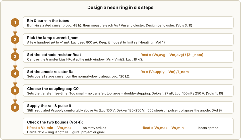
The recipe distilled — the long version is Vol 4, with tube data from Vol 3, the supply from Vol 9, and burn-in from Vol 11. Figure 15.1 is this same flow as a card.
- Bin & burn-in. Burn new/NOS lamps in at rated current (Luc: 48 h) to stabilise
Vs/Vmand weed early failures, then measure and cluster them (Vol 11). Design per cluster. - Pick
Inom. A few hundred µA to ~1 mA; Luc chose 800 µA. Modest current limits self-heating and ageing (Vol 4). - Set
Rcat=(Vs,avg − Vm,avg) / (2·Inom)— this parks the transfer biasI·Rcatat the mid-window(Vs − Vm)/2. Luc: 18 kΩ. - Set
Ra=(Vsupply − Vm) / Inom— the overall stage current on the normal-glow plateau. Luc: 120 kΩ. - Choose
C0for clean transfer: too small stalls the hand-off, too large double-steps. Dekker: 27 nF; Luc: 100 nF / 250 V (Vols 4, 10). - Supply & pulse. A stiff, regulated
Vsupplycomfortably aboveVs(Luc 150 V; Dekker 185–250 V), collapsed by a 555 step/run pulser (Vol 9).
Then re-check the two bounds of §15.2: I·Rcat must sit below Vs,min − Vm,max (no stray
strikes) and above Vs,max − Vs,min (beats the spread). If the cluster’s spread is too wide
for both to hold at once, re-bin tighter — that, not the arithmetic, is usually the fix.
15.5 The speed ceiling
Deionisation (recovery) time is of order milliseconds, so a previously-lit stage must fully extinguish before the next pulse or the glow smears, double-steps, or stalls. That caps ordinary cold-cathode ring counting at roughly ~1 kHz (Vol 2). Specially-gassed tubes reach perhaps ~10–20 kHz; Dekker only hit ~500 kHz by dropping capacitive coupling entirely and driving the ring with fast TTL pulses through a high-voltage transistor pull-down. Neon counting is a low-speed, human-scale technique — perfect for a watchable dial or a mains-tick divider, wrong above a few kHz.
15.6 Component picks
Matches Vol 10. The passive choices below feed straight back into drift (§15.7), so they are not cosmetic.
Capacitors (coupling / timing — want low leakage, low dielectric absorption, stable value):
- Prefer polypropylene (best), then polystyrene, or C0G/NP0 ceramic for small stable values.
- Rating ≥ 250 V (≥ the rail) as a rule; Luc used 100 nF / 250 V.
- Avoid electrolytics and high-K ceramics (X7R, Y5V) in timing/coupling — leakage and dielectric absorption cause drift and jitter.
Resistors (high-value anode/cathode parts at high voltage — VCR and max working voltage matter):
- Prefer metal-film, 1 % tolerance (low VCR, low noise) for centring the tight bias — not carbon composition (high voltage-coefficient, drift, noise).
- Size wattage by
P = I²R(orV²/R) with derating. - Where a single part’s maximum working voltage is exceeded, use series resistors to share it.
15.7 Drift-hardening checklist
The Vol 7 mitigations, ranked by leverage — work down the list:
- A stiff, regulated supply (every volt of rail drift eats the margin directly).
- Bin and match tubes into tight
Vs/Vmclusters. - Burn in before final measurement — most drift is in the first hours (Vol 11 jig).
- Centre the bias at
(Vs − Vm)/2and, where you can, pick large-window tubes (ZA1002). - Prime the lamps — ambient/keep-alive light, a permanently-lit priming lamp/LED, or radioactive priming — to kill the dark effect and speed striking.
- Use low-TC, stable passives (metal-film R, film C — §15.6).
- Keep currents modest to limit self-heating.
- Add buffer/amplifier lamps for reliable carry between counters (the PA3FWM fix).
The honest caveat, from PA3FWM: even done right, individual lamps misbehave and progressive ageing
can make a neon clock unusable after 1–2 years — “fully characterising a neon lamp needs more than
just Vs and Vm.”
15.8 Dekatron drive summary
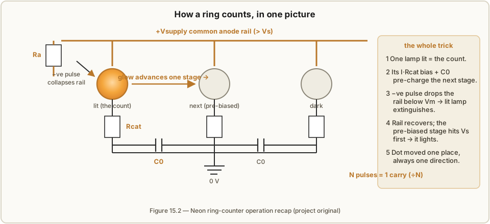
A dekatron packs a whole ring into one envelope: a central disc anode, a ring of 10 main (indicator) cathodes, and guide cathodes (one or two per gap) that walk the glow from one main cathode to the next (Vol 5).
Table 5 — 15.8 Dekatron drive summary
| Item | Value / choice |
|---|---|
| Anode | ~+400–475 V through an anode resistor |
| Cathode current | a few hundred µA to ~1 mA |
| Counting speed | ~1 kHz (specials higher) |
| Double-pulse / two-guide | needs a 2-phase guide waveform; e.g. many GC10-family counting tubes |
| Single-pulse | one guide set + internal biasing |
| Counter dekatron | display/counting current (GC10/GC10B) |
| Selector dekatron | higher cathode current for switching, not just display (GS10 family) |
| Carry | tap off a chosen cathode to clock the next decade |
Families to know: Ericsson GS10, GC10/GC10B (ETL/Mullard), Soviet OG-4/OA-4, Raytheon CK6910. Famous uses: the Harwell WITCH (dekatrons as memory) and the Bell Punch ANITA calculator.
15.9 High-voltage safety — the quick rules
The full discipline is Vol 14. The short version, and it is not optional:
⚠ Every rail in this series is ~100–450 V DC and a reservoir capacitor stays charged after power-off. That is lethal, and unlike mains it does not trip anything or announce itself.
- Prove it discharged with a meter before touching anything — assume live until measured.
- Fit a bleeder resistor across every reservoir cap.
- Keep a discharge tool (an insulated-handle resistor lead) and use it before probing.
- Single-hand rule — keep one hand in your pocket so no current path crosses your chest.
- Insulate and isolate: insulated probes, no earth-referenced surprises, respect the burn-in jig’s live sockets, and handle NOS tubes (some contain tritium/thorium) sensibly — don’t crush them.
Glossary
- Striking voltage (
Vs) — the voltage at which a dark gap breaks down and lights. - Maintaining (sustaining/extinguishing) voltage (
Vm) — the lower voltage at which a lit discharge finally goes out. AlwaysVm < Vs. - Hysteresis — the
Vs − Vmgap; the memory window that makes a lamp bistable. - Negative resistance — the region just after breakdown where voltage falls as current rises (dV/dI < 0); the basis of oscillation and regenerative switching.
- Glow discharge — the self-sustaining cold-cathode gas discharge (normal-glow plateau) a neon lamp lives on, sustained by ion bombardment and secondary emission at the cathode.
- Penning mixture — neon with a trace of argon; the argon metastable ionises neon, lowering and
stabilising
Vs. - Transfer bias (
I·Rcat) — the voltage a lit stage’s cathode current develops across its cathode resistor, which (viaC0) pre-biases the next stage to win the race to strike. - Coupling capacitor (
C0) — the small cap linking adjacent stages that carries the transfer; its size sets the transfer rise-time. - Dekatron — a cold-cathode counting tube with a whole 10-stage ring (anode + main + guide cathodes) in one envelope; shows a spinning dot of light behind a 0–9 dial.
- Guide cathode — the auxiliary cathode(s) between main cathodes in a dekatron that walk the glow one step per guide pulse (one set = single-pulse; two sets = double-pulse/two-guide).
- Selector vs. counter dekatron — a selector (e.g. GS10 family) runs higher cathode current to switch a load; a counter (e.g. GC10) is optimised for display/counting current.
- Trigger tube — a cold-cathode tube with a starter/trigger electrode that fires the main gap on a small pulse; a switching relative of the counting tubes.
- VR tube — a cold-cathode voltage-regulator/reference tube (0A2, 0B2, 0A3, 0B3, 0C3, 0D3, 150B2…) that clamps a rail to a fixed voltage via its flat glow plateau.
- Priming — deliberately supplying seed charges (ambient/keep-alive light, a pilot glow, or radioactive priming) so a lamp strikes promptly and repeatably.
- Dark effect — a neon’s
Vsrising and turning erratic in darkness for want of photo-emitted seed electrons; cured by priming. - Dielectric absorption (DA) — a capacitor’s tendency to “remember” charge, causing timing drift and jitter; a reason to avoid electrolytics/high-K ceramics in coupling/timing roles.
- Voltage coefficient of resistance (VCR) — a resistor’s value changing with applied voltage; high in carbon composition, low in metal-film — matters for the tight bias at high voltage.
- Deionisation (recovery) time — the milliseconds a lamp needs to return to a dark, un-ionised state after extinguishing; sets the ~1 kHz counting ceiling.
- Injection-locked (regenerative) divider — a division scheme that locks a relaxation/regenerative oscillator to a sub-harmonic; unlike a true counting ring it can jump to a wrong sub-harmonic if it unlocks. A neon ring is an exact integer counter; distinguish the two.
15.10 What each volume covers
- Vol 1 — Overview & the cold-cathode counting idea; the five build paths and where each lives.
- Vol 2 — How a neon lamp works: glow discharge,
Vs/Vmhysteresis, the V–I curve and negative resistance, the relaxation oscillator, photosensitivity, the speed limit. - Vol 3 — Which tubes to use: indicator neons vs. switching vs. trigger tubes; sourcing NOS; the marginal-gap problem; the binning procedure and spec table.
- Vol 4 — The ring counter’s theory of operation: common-anode topology, the transfer mechanism
step by step, all the design equations,
C0sizing, directionality, Dekker’s worked values. - Vol 5 — Dekatrons: the integrated ring, guides, single/double-pulse drive, selector vs. counter, families, operating conditions, WITCH & ANITA.
- Vol 6 — Frequency division & accuracy: the ring as an exact integer divider, jitter vs. reliability, counting vs. injection-locked division, the Philicorda case.
- Vol 7 — Drift, ageing & mitigation, with the PA3FWM failure story as the cautionary spine.
- Vol 8 — HV supplies, traditional: valve/selenium rectification, VR-tube shunt regulation, the 150B2.
- Vol 9 — HV supplies, modern: boost/flyback converters, feedback math, current limit, bleeder.
- Vol 10 — Capacitors & resistors: dielectric and DA, metal-film vs. carbon, VCR, wattage, series-R.
- Vol 11 — The burn-in / ageing jig: schematic, socket-bank, BOM, and the measure-and-bin procedure.
- Vol 12 — Worked examples & applications: Luc’s ring, Dekker’s ring, the PA3FWM clock, dekatron scalers, WITCH, ANITA, Philicorda dividers, flashers, NE-2 memory/latches, art uses.
- Vol 13 — Build it yourself: a complete buildable reference ring counter (Dekker + Luc synthesis), schematic, BOM, 555 pulser, bring-up, troubleshooting.
- Vol 14 — Safety: the ~100–450 V discipline, shock physiology, charged caps, discharge tools, the single-hand rule, NOS-tube handling.
References
- R. Dekker, “A Neon Ring Counter” / Ring Counter Variations — https://www.dos4ever.com/ring/ring.html (the design equations,
Vs/Vmhysteresis, the ZA1002, binning, deionisation and the ~1 kHz ceiling, tritium priming and its decay). - L. Small, “Neon Ring Counters” (2016) — https://lucsmall.com/2016/10/08/neon-ring-counters/ (the worked IN-3 build: clusters, 150 V / 800 µA / 18 kΩ / 120 kΩ / 100 nF, the 555 step/run pulser).
- P.-T. de Boer (PA3FWM), “A clock using neon lamps as logic elements” — https://www.pa3fwm.nl/projects/neonclock/ (the ageing/reliability caution and the buffer-lamp fix).
- J. B. Dance, Electronic Counting Circuits (London: Iliffe Books / New York: American Elsevier, 1967) — in the site’s reference library (the canonical text: cold-cathode tubes, dekatrons, VR-tube regulation).
- Manley & Buckley, “Neon Ring Counter,” Electronics, January 1950 (the original diode-steered ring counter).
- Dekatron family & VR-tube data — Ericsson Tube Technical Handbook (1964) and frank.pocnet.net datasheets (GS10/GC10B/CK6910, 0A2/0B2/0A3/0B3/0C3/0D3/150B2).
Comments (0)