Neon Ring Counters · Volume 14
Safety — the ~100–450 V Discipline
What the rail actually does to a body, why a charged cap is the real killer, and the bench habits that keep you alive
Every buildable path in this series — the indicator-neon ring of Vol 13, the switching-tube ring, the dekatron scaler, the traditional valve supply of Vol 8, the boost supply of Vol 9, the burn-in jig of Vol 11 — runs on a direct-current rail somewhere between roughly 100 V and 450 V, and that rail sits behind a reservoir capacitor that stays charged after you switch off. That is more than enough to kill you, and it is dangerous in a way that mains is not: it does not hum, it does not arc across the room to warn you, it does not trip a breaker or a residual-current device, and it waits — quietly, patiently, sometimes for many minutes — for the moment your hand crosses it. ⚠ Treat every rail in this series as lethal until you have proven it discharged with a meter. This volume is the discipline that makes the whole hobby safe: what the voltage does to a body, why the reservoir cap is the part that actually gets people, the tools and habits that neutralise it, how to build an enclosure that keeps the hazard inside, and what to do in the seconds after someone is shocked. It is not optional reading, and it is the volume to re-read before every build — not just the first.
14.1 What ~100–450 V DC does to a body
It is worth being precise about the mechanism, because the folk wisdom (“it’s the volts that kill” / “it’s the amps that kill”) is half-right in a way that hides the real danger. What injures and kills you is current through tissue, but the current you get is set by the voltage divided by whatever resistance your body offers — so both matter, and the voltages in this series are high enough that even a fairly dry contact can push a dangerous current.
14.1.1 The current is what does the damage
Your body is, electrically, mostly salt water wrapped in a variable skin resistance. Dry,
intact skin is a decent insulator — hand-to-hand it can be 10 kΩ to over 100 kΩ. But skin
resistance collapses the moment it is wet, sweaty, broken, or pressed hard against a conductor,
and once the skin is bypassed the internal body resistance hand-to-hand is only about
300 Ω to 500 Ω, with roughly 1 kΩ a sensible worst-case for a sweaty grip. Put the
rail voltages of this series across that resistance with Ohm’s law, I = V / R:
Table 1 — rail voltages of this series across that resistance with Ohm's law, I = V / R
| Rail | Worst-case R (wet, ~1 kΩ) | Current | Verdict |
|---|---|---|---|
| 150 V (Luc-Small IN-3 ring) | 1 kΩ | 150 mA | well into the lethal band |
| 250 V (Dekker-style switching ring) | 1 kΩ | 250 mA | lethal |
| 450 V (dekatron anode rail) | 1 kΩ | 450 mA | lethal |
Even the friendliest number here — 150 V across a sweaty hand-to-hand path — delivers roughly 150 mA, and it takes only a fraction of that across the chest to stop a heart. The rail does not have to be a dekatron’s 450 V to kill; the entry-level 150 V neon ring is already comfortably able to.
14.1.2 Perception, let-go, and the current that stops the heart
The commonly cited thresholds for current flowing hand-to-hand tell the story:
- Perception — you first feel current at roughly 0.5–1 mA (a little higher for DC, around 2 mA, since DC gives a warmth/tingle rather than the sharp buzz of AC).
- Let-go threshold — at roughly 10–16 mA of 50/60 Hz AC, the current drives your forearm muscles into sustained contraction (tetany) and you cannot let go of the conductor; your grip clamps onto the hazard. DC behaves differently — it tends to produce a single violent contraction at make and break rather than a continuous clamp — but do not take comfort in that: a large DC shock throws your muscles into a convulsion that can fling you off a stool, snap a hand back into something sharp, or, if the reservoir cap is in the loop, deliver a burst far larger than the steady rail current (see §14.2).
- Ventricular fibrillation — the killer. Somewhere around 50–100 mA through the chest, for as little as a fraction of a second, can throw the heart into fibrillation — a useless quiver that pumps no blood and does not spontaneously recover. This is why current across the chest — the hand-to-hand or hand-to-foot path that runs through the torso — is the one to fear, and why every rule below is really about keeping current off that path.
The takeaway: at 150–450 V, a wet hand-to-hand contact can put ten to a hundred times the fibrillation threshold through your chest. There is no margin here to be casual with.
14.1.3 Why DC behind a capacitor is uniquely sneaky
Mains AC, for all its danger, at least announces itself: it hums, it arcs, it trips an RCD or GFCI when it leaks to earth, and a breaker opens on a dead short. A charged DC rail behind a reservoir cap gives you none of those warnings:
- It does not trip anything. A residual-current device senses AC leakage to protective earth; a floating DC rail on an isolated bench gives it nothing to sense. A breaker trips on overcurrent from the mains side, long before your body’s 150 mA registers. Nothing in the system objects when the current path is you.
- It gives no warning. No hum, no smell, no visible arc until the instant of contact. A cap charged to 300 V looks, sounds, and smells exactly like one charged to 0 V.
- It persists after power-off. Kill the mains, unplug the supply, walk away for your coffee — and the reservoir cap can still be sitting at very nearly the full rail voltage when you come back. This is the trap that gets experienced people: the supply is off, so surely it’s safe. It is not.
- DC is “sticky.” Where AC crosses zero 100–120 times a second, DC is a steady push in one direction — a continuous current with no let-up, which is part of why a sustained DC contact is so hard to break away from once your muscles have clamped.
The rest of this volume is, in effect, a set of habits designed to defeat each of those four properties.
14.2 The charged reservoir capacitor — the part that actually gets people
If there is one hazard in this whole series to fix in your mind, it is the reservoir (filter) capacitor. Every supply in Vols 8 and 9 has one: a capacitor across the rail, sized to smooth the ripple, typically a few microfarads to tens of microfarads rated at or above the rail voltage. Its job is to store charge, and it does that job whether or not the supply is running. Switch off, and it holds that charge — a lethal DC reservoir with no breaker between it and your hand.
The good news is that the physics that makes it dangerous also makes it easy to tame, because a capacitor discharged through a resistor decays predictably:
$$V(t) = V_0 \cdot e^{-t / (R \cdot C)}$$
where V₀ is the initial rail voltage in volts, R is the discharge resistance in ohms, C
the capacitance in farads, t the time in seconds, and the product τ = R·C is the time
constant in seconds. The energy the cap is holding — the jolt it can deliver — is
$$E = \tfrac{1}{2} , C , V^2$$
in joules. Two worked examples bracket this series. A 10 µF reservoir at 150 V (a modest
modern boost supply, Vol 9) stores E = ½ · 10 µF · (150 V)² ≈ 0.11 J. A 4.7 µF reservoir at
450 V (a dekatron rail) stores E = ½ · 4.7 µF · (450 V)² ≈ 0.48 J. Neither number sounds
large, but delivered as a sub-second burst through your chest it is an emphatically dangerous
amount of energy — the 0.48 J dekatron cap is the kind of jolt that leaves a burn and can stop a
heart.
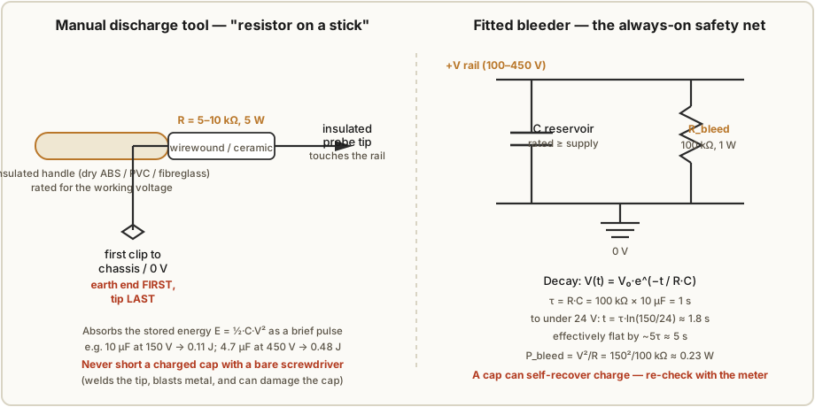
The always-on defence is a bleeder resistor, and Vol 9 already specs one across the boost supply’s reservoir; fit the equivalent on any traditional supply too. A bleeder is simply a resistor permanently wired across the reservoir so that, the instant the supply stops driving the rail, the cap drains itself through the resistor. Size it from the two equations above. Take the 10 µF / 150 V rail with a 100 kΩ bleeder:
- Time constant:
τ = R·C = 100 kΩ × 10 µF = 1 s. - Time to fall below a “safe-to-touch” ~24 V:
t = τ · ln(V₀/V_f) = 1 s · ln(150/24) ≈ 1.8 s. - Effectively flat by about
5τ ≈ 5 s. - Standing power it burns while the supply runs:
P = V²/R = (150 V)² / 100 kΩ ≈ 0.23 W— so a 1 W resistor runs cool with margin.
That is the trade every bleeder makes: small enough resistance to drain the cap in seconds, large enough to not waste power or load the supply. A few seconds of drain is the sweet spot — fast enough to be useful, slow enough that a 1 W part suffices. For higher rails scale the value so the standing power and the drain time both stay sensible (a 450 V rail wants a higher-value, higher-voltage-rated bleeder, often two resistors in series to stay under each part’s maximum working voltage — see Vol 10 on the series-resistor trick).
⚠ A bleeder is a safety net, not a licence to trust it. Bleeders fail open (they are just a resistor, and a cracked one goes to infinite resistance silently), solder joints break, and — the subtle one the brief flags — a capacitor can partially self-recover charge after being discharged. This is dielectric absorption (also called soakage): charge trapped deep in the dielectric slowly re-emerges after the plates are drained, so a cap you shorted to 0 V a minute ago can be sitting at tens of volts again when you come back. The rule that follows from all of this: never assume the bleeder did its job. Discharge it yourself with a tool, prove it dead with a meter, and if you leave the bench and come back — prove it dead again.
14.3 The working discipline
Safety at these voltages is not one gadget; it is a short list of habits practised every time, so that no single lapse is fatal. None of them is difficult. All of them are non-negotiable.
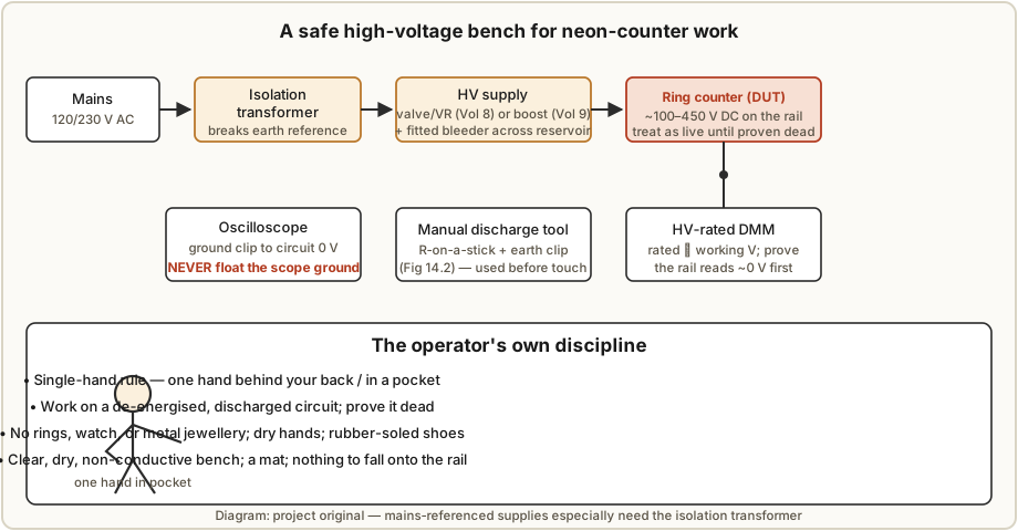
- The single-hand rule. Keep one hand behind your back or in a pocket whenever a live or possibly-live HV rail is exposed. The point is geometric: a shock through one hand to the same arm, or one hand to a foot, is bad — but a shock hand-to-hand across the chest runs the current straight through your heart, and that is the path that fibrillates. One hand in a pocket means there is no return path across your torso. This is the single most valuable habit in the volume.
- Work de-energised. The default state for touching a circuit is off, unplugged, and discharged. Live probing is a deliberate, considered exception (§14.5), not the normal way to poke around.
- Prove it dead. After switch-off and after discharging, put an HV-rated meter across the reservoir cap and the rail and confirm it reads ~0 V before you touch anything. “The supply is off” is not proof; the meter is. Prove-dead, not assume-dead — every time.
- A fitted bleeder plus a manual discharge tool. The bleeder (§14.2) drains the cap automatically; the manual tool (§14.4) is what you actively touch to the rail to be sure, because you never trust the bleeder alone.
- Insulated probes and HV-rated tools. Your meter, its leads, and any probe must be rated comfortably above the working voltage. Use probes with finger guards; keep the uninsulated tip short.
- No floating scope grounds. An oscilloscope’s ground clip is bonded to mains protective earth. Clip it to a point that is actually at circuit 0 V, and never “float” the scope by defeating its earth pin to move the ground clip somewhere convenient — that puts the whole metal chassis of the scope (and every exposed BNC shell) at whatever voltage you clipped to, which is how people electrocute themselves through the test gear. If you must reference the scope to a non-ground node, use a proper differential probe or an isolation-rated setup, never a floated chassis.
- An isolation transformer for mains-referenced supplies. The traditional valve/VR-tube supply of Vol 8 derives its rail directly from a mains transformer, and some vintage designs are only lightly isolated. Feed any mains-referenced or transformerless supply through a bench isolation transformer before you work on it: it breaks the connection between your circuit’s “ground” and mains earth, so touching one node no longer completes a circuit through the building’s wiring and your feet. (It does not make the rail safe to touch — it removes the earth-referenced path, that’s all.)
- One hand in a pocket, no jewellery, dry and clear. Take off rings, watch, and any metal bracelet — a ring across a rail is a dead short through your finger. Dry your hands. Wear rubber-soled shoes and, if you have one, stand on an insulating mat. Keep the bench clear, dry, and non-conductive — no puddle of solder-flux, no stray offcuts of wire, nothing metallic that can slump onto the rail while your attention is elsewhere.
14.4 Building the manual discharge tool
The manual discharge tool is the cheapest life-saving device on the bench, and you should build one before you build any supply. It is a current-limiting resistor on an insulated handle — never a bare screwdriver. Shorting a charged reservoir cap with bare metal welds the tip, blasts a spray of vaporised metal, stresses the cap (and can rupture an electrolytic), and does nothing to limit the ferocious peak current; the resistor tames all of that into a controlled few-second drain.
- Resistor value: 5 kΩ to 10 kΩ. Small enough to drain the reservoir in well under a
second (with a 10 µF cap and 10 kΩ,
τ = 0.1 s, so it’s flat in about half a second), large enough to hold the peak current sane — at 450 V through 10 kΩ the initial current is only 45 mA into the resistor, not an arc. - Resistor wattage: the resistor must absorb the whole stored energy
E = ½·C·V²as a pulse. The worst case in this series (the 4.7 µF / 450 V dekatron cap, ~0.48 J) is trivial for a 5 W wirewound or ceramic part to swallow, and the generous wattage also copes with repeated discharges without cooking. A 5 W part is the right call. - Handle: a dry, insulating rod — ABS, PVC, or fibreglass — long enough to keep your hand well back, rated for the working voltage. The uninsulated probe tip is the only exposed metal.
- Earth lead first, tip last. Fit a flying lead with a crocodile clip from the resistor’s far end. Clip the earth lead to the chassis / circuit 0 V first, then touch the probe tip to the live rail — so that when the tip lands there is already a defined return path through the resistor, not through you. Hold the tip on the rail for a couple of seconds, then move to the reservoir cap’s terminals directly and hold again. Then, and only then, put the meter on it and prove it dead.
The right-hand panel of Figure 14.1 shows the fitted bleeder that complements the tool; the left-hand panel is the tool itself.
FIGURE SLOT (pending) — Photo of the actual bench discharge tool: a 5 kΩ / 5 W wirewound resistor heat-shrunk to an insulated probe with a flying earth lead and crocodile clip, laid beside an HV-rated DMM and a pair of insulated probes. (Jeff’s own bench hardware.)
14.5 Live work, when it is unavoidable
Sometimes you genuinely must probe a running supply — to set a boost converter’s feedback trim (Vol 9), or to watch a transfer pulse march around the ring on a scope. Live HV work is a deliberate, slowed-down mode, not the default:
- Do it single-handed, always. Set up the probe, then keep the second hand in your pocket for the whole measurement.
- Clip the scope/meter ground to 0 V while the supply is off, then power up. Never move a ground clip on a live HV rail.
- Use a differential probe for anything referenced to a node that is not true ground.
- Have the isolation transformer in circuit for any mains-referenced supply.
- Keep the other hand and your torso out of the geometry — no leaning across the live board.
- When you are done, power down and go straight back to the discharge-and-prove-dead routine before you touch anything.
14.6 Enclosure and insulation for a finished ring counter
A ring counter you actually keep and run is a different safety problem from one on the bench: the danger has to be contained so that ordinary use — plugging it in, watching the dot march, someone’s curious finger — never reaches the rail. The governing ideas are creepage and clearance, and they matter more than beginners expect at these voltages.
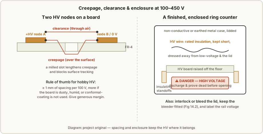
- Clearance is the shortest distance through air between two conductors at different potentials; creepage is the shortest distance over the surface of the insulator between them. Air breaks down at high field, and insulator surfaces can slowly “track” a conductive carbon path under voltage, dust, and humidity — so both distances have to be generous. A usable hobby rule of thumb is at least ~1 mm of spacing per 100 V, and more if the board runs dusty, humid, or uncoated. At 450 V that means comfortably over 4–5 mm between HV nodes, with margin. A milled slot cut in the board between two HV nodes both lengthens the creepage path and physically interrupts any surface-tracking path — a cheap, effective trick.
- HV wiring: use wire with insulation rated for the rail (not thin signal hookup), keep HV runs short and direct, and dress them away from low-voltage wiring and from the lid so nothing chafes into a short. Solder joints on the HV rail should be smooth blobs — sharp whiskers concentrate field and invite corona.
- Standoffs and mounting: raise the HV board off the case floor on insulating standoffs so no HV pad rests against the enclosure. If the case is metal, bond it to protective earth so a fault to the case trips upstream rather than making the case live.
- Keep the bleeder fitted in the finished unit (§14.2) so it self-discharges every time it’s switched off.
- Warning labels: a plain ⚠ DANGER — HIGH VOLTAGE label on the inside of the lid, plus the rail voltage marked, so that future-you (or whoever opens it next) is reminded to discharge and prove-dead before reaching in. If the lid can be interlocked to bleed the rail on opening, better still.
14.7 The burn-in jig’s specific hazards
The burn-in jig of Vol 11 deserves its own paragraph because it concentrates the danger: it is, by design, a bank of live sockets on a current-limited HV rail, sitting open on the bench for hours or days while you condition tubes. Its particular traps:
- Every socket is live. Unlike a finished counter in a case, the jig’s sockets are exposed and energised for the whole burn-in. Treat the socket bank as a live 100–450 V surface at all times.
- You will want to swap tubes. The temptation to pull a burned-in tube and drop in the next one while the rail is up is exactly how people get bitten. Power down, discharge, prove dead, then handle the sockets — every swap. Design the jig so this is quick (a clearly labelled master switch and an easy discharge point) so the safe path is also the convenient one.
- It runs unattended. Because burn-in is a multi-hour or multi-day affair, the jig is often left running. Give it a fully enclosed or guarded live section, a fused/current-limited rail, a fitted bleeder, and a clear label — nobody should be able to brush the socket bank in passing, and it should not be able to start a fire if a tube fails short. Never leave a bare-socket jig live and unattended.
- Heat. Sockets, series resistors, and the supply run warm for a long time; keep the jig on a non-flammable surface with airflow, and size the socket series resistors’ wattage with derating (Vol 10).
14.8 Handling NOS tubes
The tubes themselves carry a couple of hazards unrelated to the rail:
- Glass and vacuum/low-pressure envelopes. Indicator neons and switching tubes are small and robust, but dekatrons and larger cold-cathode tubes are evacuated or low-pressure glass envelopes that can crack or implode if dropped or knocked — wear eye protection when handling bare tubes, and store and transport them padded. A cracked tube is scrap; don’t try to run it.
- Radioactive priming. Some switching and counting tubes are deliberately primed with a small radioactive source to speed and stabilise striking — the Philips ZA1002 uses tritium (a low-energy beta emitter, 12.3-year half-life; Vol 3), and older stock may use krypton-85, nickel-63, or thorium. Intact, these are low-hazard: the sealed envelope contains the (very weak) emission, and normal handling is fine. The rule is simply do not break the envelope and do not inhale or ingest the contents — a broken tritium tube should be ventilated away from and cleaned up carefully, not handled casually. Wash your hands after handling grubby NOS stock regardless.
- Old, dirty, and mystery-labelled stock. NOS tubes arrive dusty and sometimes mislabelled. Clean them dry, read the actual type before trusting a datasheet, and remember that decayed priming makes old tubes strike erratically (Vol 3, Vol 7) — an electrical nuisance, not a safety issue, but worth knowing before you blame the supply.
14.9 If someone is shocked
Have this clear in your head before it is needed, because the right first action is counter-intuitive:
- Do not grab them. If they are still in contact with the rail and you touch them, the current path now includes you. Your first move is to kill the power — hit the master switch, pull the plug, or trip the breaker.
- If you cannot cut power instantly, knock them clear of the conductor with something non-conductive and dry — a wooden or plastic broom handle, a length of dry timber — never your bare hand.
- Once they are clear and the power is off, call emergency services. A shock across the chest can cause a delayed cardiac arrhythmia even if the person seems fine, so any HV shock through the torso is a call-an-ambulance event, not a “walk it off” one.
- If they are unresponsive and not breathing normally, start CPR and use an AED if one is available; keep going until help arrives. (This is the reason the old advice never work alone on lethal HV exists — someone has to be able to cut the power and call for help.)
- Treat burns at the entry and exit points as the real injuries they are, and mention to the responders that it was a high-voltage DC shock — the internal path matters to their assessment.
Knowing this list is part of being allowed to switch the bench on. If you build the supplies in this series, learn basic CPR; it is the other half of HV safety.
14.10 The checklists
Two short lists to run from memory, plus the discharge procedure they refer to. Print them and tape them inside the bench cupboard.
Before you power on
- Bench clear, dry, non-conductive; mat down.
- Rings, watch, metal bracelets off; hands dry.
- Bleeder fitted and intact across the reservoir; manual discharge tool within reach.
- HV wiring dressed clear; no stray metal on the board; lid/guard where practical.
- Isolation transformer in circuit for any mains-referenced supply (Vol 8).
- Scope/meter grounds clipped to true circuit 0 V now, before power-up; never floated.
- One hand free to hit the master switch; you know where the off switch is.
Before you touch anything
- Supply off and unplugged.
- Discharge the reservoir with the manual tool (procedure below).
- Prove it dead — HV-rated meter across the reservoir and the rail reads ~0 V.
- Single-hand rule engaged — one hand in a pocket for the first contact.
- If you left the bench and came back: prove it dead again (self-recovery, §14.2).
The discharge procedure (step list)
- Switch the supply off and unplug it from the mains.
- Wait a few seconds for the fitted bleeder to do most of the work.
- Pick up the manual discharge tool. Clip its earth lead to chassis / circuit 0 V first.
- Touch the probe tip to the live rail and hold for ~2 s.
- Move the tip directly to the reservoir capacitor’s terminals and hold for ~2 s.
- Set the tool down. Put the HV-rated meter across the reservoir and the rail; confirm ~0 V.
- Only now is it safe to work — single-handed. If you step away and return, repeat from step 3.
The tubes are beautiful and the glowing dot is gentle to watch. The electricity behind it is not gentle at all, and the difference between a lifelong hobby and a single very bad afternoon is nothing more than practising the short list above, every single time.
14.11 14.x References
- J. B. Dance, Electronic Counting Circuits (London: Iliffe Books / New York: American Elsevier, 1967) — cold-cathode supplies, VR-tube regulation, and the reservoir/bleeder practice underlying the traditional supply (Vol 8). in the site’s reference library
- R. Dekker (dos4ever), “A Neon Ring Counter” — https://www.dos4ever.com/ring/ring.html — rail voltages (185–250 V) and reservoir/bleeder context for the switching-tube ring.
- L. Small, “Neon Ring Counters” (2016) — https://lucsmall.com/2016/10/08/neon-ring-counters/ — the 150 V rail and 100 nF / 250 V coupling caps of the worked IN-3 build.
- P.-T. de Boer (PA3FWM), “A clock using neon lamps as logic elements” — https://www.pa3fwm.nl/projects/neonclock/ — the +151/+157 V rails and 150B2-regulated supply that this discipline protects.
- This project’s companion volumes: Vol 8 (traditional HV supply, isolation), Vol 9 (modern boost supply + the specified bleeder), Vol 10 (resistor wattage, max working voltage, the series-resistor trick), Vol 11 (the burn-in jig’s live socket bank), Vol 13 (the reference ring counter this safety discipline is written to protect).
- General shock-physiology thresholds (perception ~0.5–1 mA, let-go ~10–16 mA AC, fibrillation ~50–100 mA across the chest) and body-resistance figures are the standard values from electrical- safety literature (e.g. IEC 60479-1 guidance), stated here in round numbers for bench use.
Comments (0)