Neon Ring Counters · Volume 13
Build It Yourself — a Reference Neon Ring Counter
A complete, buildable 10-stage IN-3 ring counter on a 150 V rail: schematic, design-equation walkthrough, 555 step/run pulser, BOM, bring-up, and troubleshooting
Everything in the first twelve volumes has been leading here: a real thing you can put on
the bench, feed pulses to, and watch count in glowing gas. This volume synthesises the two
best modern sources — Ronald Dekker’s design equations (Vol 4) and Luc Small’s
measured component values for a bag of real surplus IN-3 neons (Vols 3 and 11) — into
one coherent 10-stage ring counter running on a 150 V rail, driven by a small
555-based step/run pulser through a high-voltage transistor. It is deliberately
conservative: indicator neons with a marginal Vs−Vm window are the hardest lamps to make
count, so if the design works with binned IN-3s it will work with almost anything, and the
same board reused with wider-window switching tubes (Vol 3) only gets more forgiving. What
follows is a build, not a study — a schematic you can lay out, an arithmetic walkthrough
that picks every value with units shown, a bill of materials, a power-up sequence, and a
troubleshooting table keyed to the failure modes Vol 4 catalogued. ⚠ The ring runs on a
150 V DC rail behind a charged reservoir capacitor; that is lethal, and it does not warn
you — treat every node as live until you have proven it discharged with a meter, and read
the full safety discipline in Vol 14 before you power anything.
13.1 Design goals and the whole schematic
The target is the simplest ring that actually behaves: ten stages in a closed loop, one lamp lit at a time, the glow advancing exactly one stage per input pulse and dividing the input frequency by ten, with a carry pulse available off any cathode for cascading a second decade later. The design goals, in priority order, are: (1) reliable single-stepping with cheap binned indicator neons — no skips, no double-steps; (2) a single low-current 150 V rail shared with nothing else, so supply drift is the only supply variable; (3) all steering done at low voltage where it is safe to probe — the count pulse is generated by 555 timers on a 9 V logic rail and injected into the high-voltage ring through one transistor; and (4) every value a standard E12/E24 part so the whole thing is a Saturday-afternoon build from a normal parts drawer plus a box of conditioned lamps.
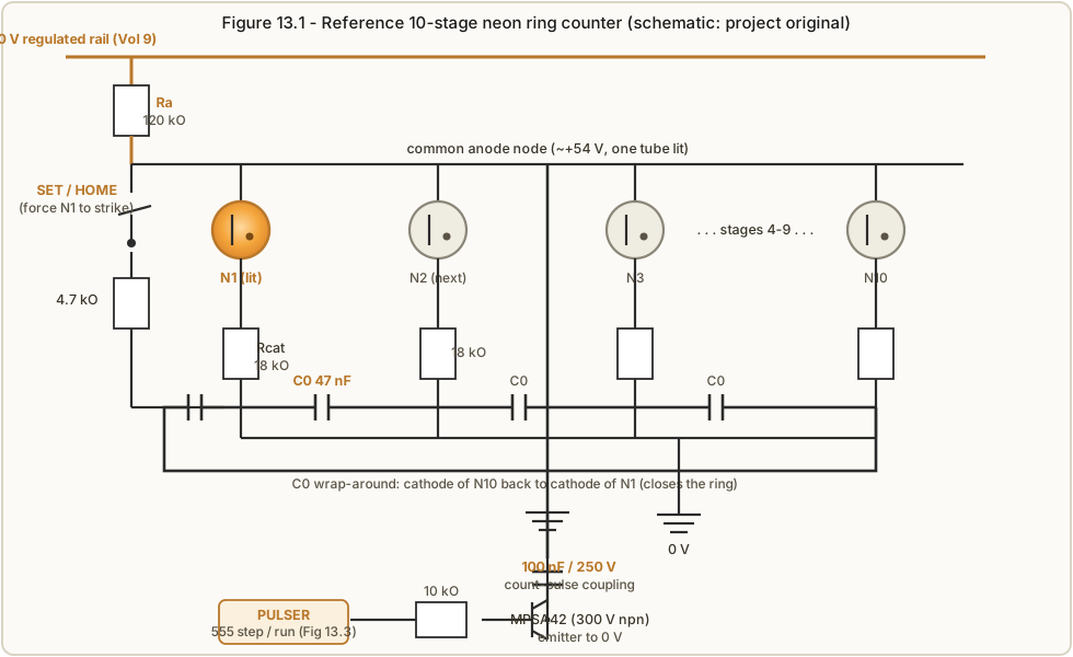
The complete circuit is shown in Figure 13.1. Read it as three blocks. The ring proper
is the common-anode topology of Vol 4: the +150 V rail feeds a single anode resistor
Ra into a common anode node that all ten neons share; each neon drops down to its own
cathode resistor Rcat to ground; and each cathode node is tied to the next cathode
node by a small coupling capacitor C0, with a tenth cap wrapping from stage 10 back to
stage 1 to close the ring. The injector is the high-voltage transistor at the bottom — an
MPSA42 whose collector couples to the common anode node through a 100 nF / 250 V
capacitor; when the transistor is pulsed on, it yanks a fast negative step onto the anode,
collapsing it below the maintaining voltage and extinguishing the lit lamp so the ring can
step. The SET / HOME pushbutton at the left forces stage 1 to strike on power-up so you
always start from a known lamp. The pulser that drives the transistor’s base is a separate
low-voltage board (Figure 13.3), covered in §13.4.
The count sequence is exactly the mechanism Vol 4 worked through, so only the one-sentence
version belongs here: the lit lamp’s cathode current develops a transfer bias I·Rcat
on its cathode, C0 carries a slice of that bias onto the next stage’s cathode, and when
the injector momentarily collapses the anode and then lets it recover through Ra, the
pre-biased next stage reaches its striking voltage Vs first and lights — so the glow walks
one stage, always in the same direction. Everything below is about choosing Ra, Rcat and
C0 so that this happens every single time.
13.2 The design-equation walkthrough — picking real values
This is the heart of the build, and it is pure arithmetic once you have measured your lamps.
Bin and burn-in a batch of IN-3s on the Vol 11 jig first; the numbers here use Luc Small’s
lower cluster of 14 lamps as the worked example, because it is real measured data for the
exact tube this design targets. After a 48-hour burn-in that cluster measured striking
voltage Vs = 73–77 V (average Vs,avg ≈ 75 V) and maintaining voltage Vm = 38–42 V
(average Vm,avg ≈ 40 V). Everything else follows from those four numbers plus one free
choice — the lamp operating current Inom.
Step 1 — choose the operating current. Indicator neons sit happily on the normal-glow
plateau at a few hundred microamps to a milliamp; run them too hard and they sputter and age,
too soft and striking gets erratic. Following Luc, take Inom = 800 µA. This is the one
value you pick by judgement; everything else is forced by it.
Step 2 — the cathode resistor Rcat sets the transfer bias. The transfer bias must be
large enough to make the next lamp win the race to strike, but small enough that it never
strikes a lamp on its own. Dekker’s two bounds and the ideal centre (Vol 4) are:
- lower bound (transfer must beat the lamp-to-lamp
Vsspread):I·Rcat > Vs,max − Vs,min = 77 V − 73 V = 4 V - upper bound (bias must not itself strike a dark lamp):
I·Rcat < Vs,min − Vm,max = 73 V − 42 V = 31 V - ideal centre:
I·Rcat ≈ (Vs,avg − Vm,avg)/2 = (75 V − 40 V)/2 = 17.5 V
So the usable window for the transfer bias is 4 V to 31 V, with an ideal near 17.5 V. In
resistance, the ideal is Rcat = (Vs,avg − Vm,avg)/(2·Inom) = 35 V / (2 × 800 µA) = 21 875 Ω.
That is not a standard value, and — exactly as Luc found working from his own per-lamp
averages, which came out a shade tighter (near 16.9 kΩ) — the sensible standard part just
below is Rcat = 18 kΩ. That gives an actual transfer bias of
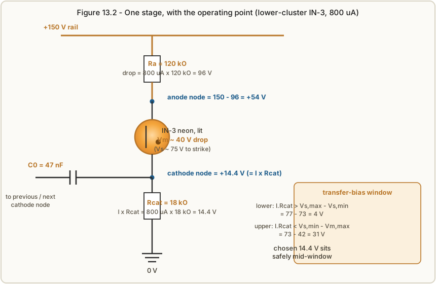
I·Rcat = 800 µA × 18 kΩ = 14.4 V,
which sits comfortably mid-window (well above the 4 V floor, well below the 31 V ceiling) and biases very slightly toward reliable striking rather than toward stray strikes — the safer side to err on with marginal lamps. Use 1 % metal-film here (Vol 10): the tight window rewards centred, low-drift resistors.
Step 3 — the anode resistor Ra sets the current. With the operating point known, Ra
simply drops the rail down to the lamp. The lit lamp clamps to its maintaining voltage Vm,avg
≈ 40 V and its cathode sits at I·Rcat = 14.4 V above ground, so the anode node must sit at
Vm,avg + I·Rcat = 54.4 V, and Ra carries the difference from the rail:
Ra = (Vsupply − Vm,avg − I·Rcat)/Inom = (150 V − 40 V − 14.4 V)/800 µA = 95.6 V / 800 µA ≈ 119.5 kΩ.
The nearest standard value is Ra = 120 kΩ (Luc’s exact figure was 120.6 kΩ). Check the
power: P = I²·Ra = (800 µA)² × 120 kΩ ≈ 77 mW, so a 1/4 W metal-film part is fine, though a
1/2 W gives comfortable derating at 150 V (Vol 10 on working-voltage limits). Figure 13.2
draws the resulting operating point on a single stage: anode node +54 V, lamp drop 40 V,
cathode node +14.4 V, with the transfer-bias window shown alongside.
Step 4 — the coupling capacitor C0 sets the transfer. C0 is the memory that hands the
bias forward, and its size is a compromise Vol 4 named: too small and the next stage never
gets enough charge to win (the ring stalls or skips); too large and the bias bleeds across
and double-steps (the glow jumps two lamps). Dekker used 27 nF on faster switching tubes;
Luc’s slower indicator-neon ring wanted more coupling. A good middle for this design is
C0 = 47 nF, film, rated ≥ 250 V (Vol 10: polypropylene or polystyrene, never electrolytic
or high-K ceramic — leakage and dielectric absorption here show up directly as jitter). Treat
C0 as the one value to tune on the bench: if the ring skips, step up toward 68 nF; if it
double-steps, step down toward 33 nF. The Ra·C0 recovery time constant — 120 kΩ × 47 nF ≈ 5.6 ms — must be comfortably longer than the injector pulse and shorter than the input
period, which is why the run rate is kept low (§13.4).
To summarise the arithmetic in one place: Inom = 800 µA, Rcat = 18 kΩ (I·Rcat = 14.4 V),
Ra = 120 kΩ, C0 = 47 nF, Vsupply = 150 V. These are the numbers on the schematic and in
the BOM. If you binned the middle or upper IN-3 cluster instead (higher Vs/Vm), rerun
Steps 2–3 with those averages and raise the rail so it still clears Vs,max with margin — the
method is identical, only the four measured voltages change.
13.3 The supply — a 150 V rail (see Vol 9)
The ring needs one thing from its supply: a stable, current-limited +150 V DC rail with a bleeder resistor across the reservoir capacitor. It is built and explained in full in Vol 9 (the modern boost/flyback approach) or Vol 8 (the traditional VR-tube approach); this volume only specifies what the ring demands of it.
- Voltage: +150 V DC, set-point trimmed to ±1 V. Every volt of rail drift moves the design margins directly (Vol 7), so a regulated boost with a feedback divider — not an unregulated multiplier — is strongly preferred. A ±5 % rail check (142–158 V) is part of bring-up (§13.7).
- Current: the ring draws only one lamp’s worth at a time — 800 µA on the plateau, plus leakage and the injector’s brief cap-charging surge — so budget a modest 5–10 mA of rail capability for headroom and any future second decade. This is a low-power rail; a small nixie- style boost module is overkill in the best way.
- Current limit + bleeder: limit the supply so a dead short can’t dump the full reservoir through the ring, and fit a bleeder (e.g. 220 kΩ / 2 W across the reservoir) so the rail falls to a safe voltage within a few seconds of switch-off. The bleeder is a safety part, not an optional one — Vol 14.
Keep the 150 V rail and the 9 V logic rail on separate regulators with a single shared 0 V star (Figure 13.4); the only wire that crosses between the high-voltage and low-voltage domains is the injector’s 100 nF coupling cap.
13.4 The pulser — 555 single-step and 555 run
You drive the ring with pulses, and the friendliest way to bring one up is to advance it one step at a time by hand, watch the dot move, and only then let it run. The pulser (Figure 13.3) therefore gives you both, selected by a switch, and both are built from the humble 555 on the low-voltage rail — all the danger stays on the far side of the injector transistor.
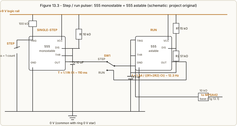
Single-step — 555 monostable. Wired as a one-shot, the 555 emits a single clean pulse each
time you press the STEP button, long enough to see but too short to matter to the ring. With
timing parts Rt = 10 kΩ and Ct = 10 µF the pulse width is
T = 1.1 · Rt · Ct = 1.1 × 10 kΩ × 10 µF = 0.11 s = 110 ms,
matching Luc’s single-step one-shot. The long pulse also debounces the button for free. Each press = exactly one count, which is precisely what you want while you are learning the ring’s behaviour and, later, while you are hunting a fault.
Run — 555 astable. For continuous counting the astable free-runs at a deliberately slow
rate so the dot is watchable and the ring’s ~1 kHz ceiling (Vol 2) is never in sight. With
R1 = 15 kΩ, R2 = 51 kΩ and Ct = 1 µF,
f = 1.44 / ((R1 + 2·R2)·Ct) = 1.44 / ((15 kΩ + 102 kΩ) × 1 µF) = 1.44 / (0.117 s) ≈ 12.3 Hz,
i.e. Luc’s ~12.5 Hz run rate — a shade over one lap of the ten-stage ring per second, slow
enough to follow the dot with the eye. Swap Ct for a bigger cap to crawl, or a smaller one to
speed up toward the tube limit.
Selecting and injecting. A single-pole switch SW1 routes either 555 output to a 10 kΩ
base resistor driving the MPSA42. On each pulse the transistor saturates, and its collector
— coupled to the common anode node through the 100 nF / 250 V cap — dumps a fast negative-
going step onto the anode, collapsing it below Vm for a millisecond or two. The lit lamp
extinguishes; as the anode recovers through Ra, the pre-biased next stage strikes first and the
glow advances. The MPSA42 is the right transistor here because it is a cheap 300 V NPN — the
anode swings tens of volts and the cap can present transients, so the high V(CEO) rating gives
margin. Keep the whole pulser on its own ground return to the 0 V star so its switching current
never flows through the sensitive cathode nodes.
13.5 Building it — point-to-point, perfboard, or PCB
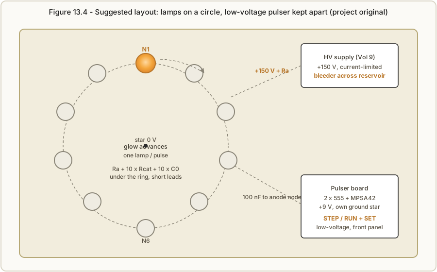
This is a low-parts-count, low-current circuit, so any construction method works; the only
real constraints come from the high voltage and the tight bias window. Figure 13.4 shows a
suggested physical arrangement: the ten lamps on a circle so the advancing dot literally
rotates (the whole point of a ring counter), with Ra, the ten Rcats and the ten C0s tucked
underneath on short leads, and the low-voltage pulser kept as a separate board near the front
panel with the STEP/RUN and SET controls.
Practical construction notes:
- Perfboard / point-to-point is the natural first build. Lay the lamps on the circle,
keep the cathode-node wiring short (that is where the transfer bias lives — long floppy leads
add stray capacitance that muddies
C0), and give the 150 V anode rail generous creepage from the 0 V and logic traces. - Grounding: one star point. The ring’s cathode returns, the injector emitter, and the pulser 0 V all meet at that star and nowhere else, so pulser switching current does not develop a voltage across a cathode node and false-trigger a transfer.
- High-voltage hygiene: ≥ 250 V-rated caps everywhere on the ring side; keep the reservoir’s bleeder (Vol 9) fitted; and route the 150 V rail as a single obvious wire you can spot and respect. ⚠ Nothing on the ring side is safe to touch with the rail up.
- A KiCad project for both this reference ring and the Vol 11 burn-in jig will live in
03-outputs/manufacturing/kicad/once the board is laid out and verified; treat the schematic here (Figures 13.1–13.3) as the source of truth until then, and the layout of Figure 13.4 as the intended floorplan.
FIGURE SLOT 13.5 — the finished reference ring on perfboard: the ten IN-3s arranged on their circle with the passive ring beneath, and the separate low-voltage pulser board, shot once built.
FIGURE SLOT 13.6 — the ring running in a darkened room: a time-exposure of the dot mid-lap, showing one lamp lit and the just-extinguished neighbour still faintly glowing.
13.6 Bill of materials
Quantities are for a single 10-stage ring plus its step/run pulser; the 150 V supply is a separate build (Vol 9) and is not itemised here beyond the rail spec. All resistors 1 % metal- film unless noted; all ring-side capacitors film, rated ≥ 250 V.
Table 1 — 13.6 Bill of materials
| Ref | Qty | Value / part | Notes |
|---|---|---|---|
| N1–N10 | 10 | IN-3 (or NE-2) neon, binned + burned-in | Lower cluster: Vs 73–77 V, Vm 38–42 V (Vol 11) |
| Ra | 1 | 120 kΩ, 1/2 W metal-film | Anode resistor; ~77 mW dissipation |
| Rcat | 10 | 18 kΩ, 1/4 W metal-film, 1 % | One per stage; sets 14.4 V transfer bias |
| C0 | 10 | 47 nF film, 250 V (polypropylene/polystyrene) | Coupling; tune 33–68 nF on the bench |
| Cinj | 1 | 100 nF film, 250 V | Injector coupling to anode node |
| Q1 | 1 | MPSA42 (300 V NPN) | High-voltage pulse injector |
| Rb | 1 | 10 kΩ, 1/4 W | MPSA42 base resistor |
| Rset | 1 | 4.7 kΩ, 1/4 W | SET/HOME series resistor to N1 cathode |
| SW_set | 1 | Momentary pushbutton | SET / HOME (force N1 to strike) |
| U1 | 1 | 555 timer (monostable) | Single-step one-shot |
| U2 | 1 | 555 timer (astable) | ~12.5 Hz run oscillator |
| Rt / Ct (U1) | 1 / 1 | 10 kΩ / 10 µF | T ≈ 110 ms one-shot |
| Rtrig / SW_step | 1 / 1 | 100 kΩ / momentary pushbutton | STEP trigger + pull-up |
| R1 / R2 / Ct (U2) | 1 / 1 / 1 | 15 kΩ / 51 kΩ / 1 µF | f ≈ 12.3 Hz astable |
| SW1 | 1 | SPDT toggle | STEP / RUN select |
| — | — | +150 V rail (Vol 9) + 220 kΩ/2 W bleeder | Current-limited; +9 V logic rail for the 555s |
13.7 Bring-up
Bring the ring up cold, slow, and single-stepped, in this order. Do not skip the rail check; the whole design assumes 150 V ±5 %. ⚠ The rail is lethal — one hand behind your back, meter before fingers, bleeder proven, Vol 14.
- Pulser first, rail off. Power only the 9 V logic rail. Scope or LED-probe the MPSA42 base node: press STEP and confirm one ~110 ms pulse per press (monostable); flip SW1 to RUN and confirm a steady ~12.5 Hz square wave. Fix the low-voltage side completely before any high voltage exists on the bench.
- Set the rail. With the ring disconnected, bring up the 150 V supply into its bleeder only and trim the set-point to +150 V. Verify current limit behaves and that the rail falls to a safe voltage within a few seconds of switch-off (bleeder working). Only then connect the ring.
- Verify one lamp lights. Power the rail with the pulser idle. Press SET / HOME — stage 1
should strike and stay lit (its cathode pulled toward ground through the 4.7 kΩ makes it win).
Exactly one lamp should glow. If none strike, the rail or
Rais wrong; if several strike,Rais too small or the rail too high (§13.8). - Single-step and watch the dot advance. With SW1 on STEP, press once. The glow should jump
to the adjacent stage, once per press, always the same direction. Walk it a full lap of
ten presses and confirm it returns to stage 1 — that closed lap is the ring working. This is
where you tune
C0: skips mean too little coupling (raise toward 68 nF), double-jumps mean too much (lower toward 33 nF). - Run. Flip SW1 to RUN. The dot should rotate smoothly at ~1.2 laps per second with no skips, stalls, or reversals over minutes. Nudge the rail ±5 % (142–158 V) and confirm it still counts clean at both extremes — that margin is your reliability insurance (Vol 7).
- Tap a carry (optional). For a decade divider, take a carry pulse off one cathode node (e.g. stage 10) into the next decade’s injector, exactly as this stage’s pulser drives this ring.
FIGURE SLOT 13.7 — bring-up in progress: the meter reading +150 V on the rail with one lamp lit, and a scope trace of the injector pulse collapsing the anode node, captured during a single-step test.
13.8 Troubleshooting
The symptoms map cleanly onto the Vol 4 failure modes; each fix points at the volume that explains it. Change one thing at a time and re-run the single-step test (§13.7 step 4).
Table 2 — 13.8 Troubleshooting
| Symptom | Likely cause | Fix (see) |
|---|---|---|
| Won’t strike at all — every lamp dark | Rail below Vs,max; Ra too large; unconditioned/unprimed lamps (dark effect) | Confirm rail = 150 V; verify Ra = 120 kΩ; burn-in + prime the lamps, add ambient light or a keep-alive (Vols 7, 11) |
| Several lamps lit at once on power-up | Ra too small / rail too high → anode node clears Vs for dark lamps too | Raise Ra or trim the rail down; re-check the +54 V anode-node figure (§13.2, Vol 4) |
| Stalls / skips — dot drops out or jumps a lamp | C0 too small (too little transfer charge); Rcat too large (bias above the 31 V ceiling); one weak lamp | Raise C0 toward 68 nF; verify Rcat = 18 kΩ; re-bin the offending lamp (Vols 4, 10, 11) |
| Double-steps — advances two per pulse | C0 too large; injector pulse too long/hard; rail too high | Lower C0 toward 33 nF; shorten the pulse / reduce base drive; trim rail down (Vols 4, 9) |
| Runs backwards or randomly | Coupling to the wrong neighbour; stray capacitance / ground loop swamping C0; too-fast run rate | Recheck C0 orientation cathode→next cathode; single-point star ground; slow the run rate (Vols 4, 10) |
| Drifts over minutes/hours — margins wander | Supply drift; self-heating; lamp ageing; light-level (dark effect) | Stiffen/regulate the rail; keep current at 800 µA; prime against darkness; low-TC passives (Vols 7, 9, 10) |
| Erratic striking, gets worse in the dark | Photosensitivity / lost priming (esp. NOS tubes) | Add ambient light, a permanently-lit priming lamp/LED, or re-select primed lamps (Vol 7) |
If the ring single-steps perfectly but misbehaves only on RUN, suspect the injector timing or a ground loop before you suspect the lamps — the ring itself has already proven it can count. And if one particular stage is always the culprit, it is almost always that lamp, not the design: pull it, re-measure it on the Vol 11 jig, and swap in a better-matched one from the same cluster.
References
- L. Small, “Neon Ring Counters” (2016) — https://lucsmall.com/2016/10/08/neon-ring-counters/ — the measured IN-3 clusters, the 150 V / 800 µA / 18 kΩ / 120 kΩ / 100 nF values, the MPSA42 injector, and the 555 step/run pulser this build is based on.
- R. Dekker (dos4ever), “A Neon Ring Counter” — https://www.dos4ever.com/ring/ring.html — the common-anode topology, the transfer-bias design equations and bounds,
C0sizing, and the high-voltage transistor pull-down. - P.-T. de Boer (PA3FWM), “A clock using neon lamps as logic elements” — https://www.pa3fwm.nl/projects/neonclock/ — the ageing/reliability cautions behind the priming and margin advice.
- J. B. Dance, Electronic Counting Circuits (Iliffe / American Elsevier, 1967) — in the site’s reference library — the canonical cold-cathode counting reference underneath all of the above.
- Cross-references: Vol 4 (ring theory + failure modes), Vols 8–9 (the HV supply), Vol 10 (passive selection), Vol 11 (binning + burn-in), Vol 14 (safety).
Comments (0)