Neon Ring Counters · Volume 12
Worked Examples & Applications — a Gallery
A guided tour of real neon-counting and neon-dividing systems, from a two-lamp flasher to a clock, a computer, a calculator and an organ
Everything in the first eleven volumes has been theory in the service of a promise: that a box of cheap glow lamps, sorted and biased with enough care, will actually do something — count, divide, remember, keep time, make music, compute. This volume is where that promise gets cashed. It is a gallery, meant to be browsed as much as read, and it works outward from the simplest thing a neon lamp can do — flash — to the most ambitious things anyone ever built out of glowing gas: a desktop calculator, a stored-program computer, and a musical organ. For each exhibit the pattern is the same. A short theory-of-operation paragraph says how the thing works and points back to the volume that derives the physics; a project-original schematic or block diagram shows the circuit at a glance; and a run of photograph slots marks where the real hardware — a dekatron spinning its orange dot, the WITCH computer at Bletchley, Luc Small’s breadboard, de Boer’s clock — will be dropped in on the later photo pass. Read it as the proof that the rest of the series is worth the trouble. ⚠ Every rail shown here except the single-lamp flasher runs at roughly 100–475 V DC behind a charged reservoir capacitor, which is lethal; Vol 14 is the safety discipline these circuits demand.
The exhibits below are ordered by ambition, and it helps to see them side by side before the
tour begins. Every one is the same physics — the Vs/Vm hysteresis of Vol 2, steered by the
transfer bias of Vol 4 — scaled up in rail voltage and tube count until it becomes a clock, a
computer, a calculator or an organ.
Table 1
| § | Exhibit | Active device | Rail | Role | Home volume |
|---|---|---|---|---|---|
| 12.1 | Relaxation oscillator / two-lamp flasher | NE-2 indicator | ~90–120 V | Oscillate, flash | Vol 2 |
| 12.2 | Luc Small’s IN-3 ring | IN-3 indicator (binned) | 150 V | Count / divide | Vols 4, 11, 13 |
| 12.3 | Dekker’s ring | Drop-shaped neons (ZA1002 tried, tritium-spoiled) | 185–250 V | Count / divide | Vols 3, 4 |
| 12.4 | PA3FWM neon-logic clock | indicator neons ×8 rings | +151/+157 V | Keep time | Vols 6, 7 |
| 12.5 | Dekatron scaler | GC10 / GS10 dekatron | +400–475 V | Count / display | Vol 5 |
| 12.6 | Harwell WITCH | 828 dekatrons | HV | Store numbers | Vol 5 |
| 12.7 | Bell Punch ANITA | cold-cathode counting tubes | HV | Calculate | Vol 5 |
| 12.8 | Philips Philicorda | ZA1001 neon dividers | HV | Divide (÷2 octaves) | Vol 6 |
| 12.9 | Neon bistable / latch gadgets | NE-2 pairs | ~90–150 V | Remember, switch | Vols 2, 13 |
| 12.10 | Art & display | any neon / dekatron | varies | Be beautiful | — |
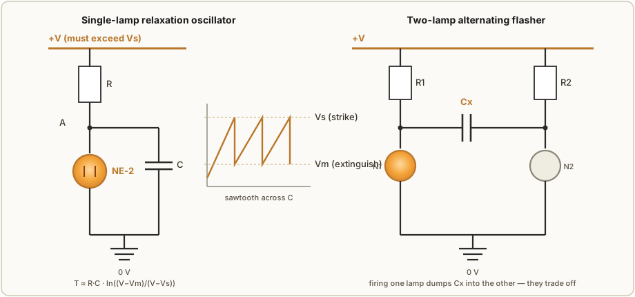
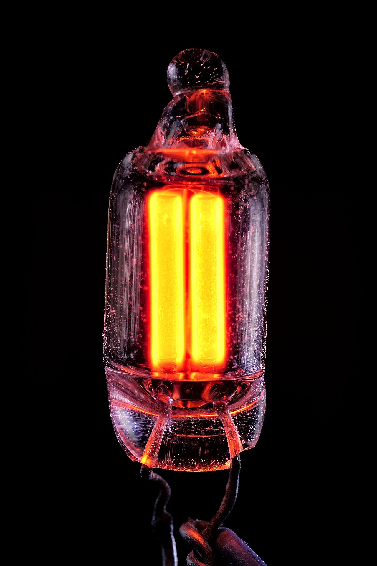
12.1 The neon relaxation oscillator and the two-lamp flasher — “hello world”
The fastest way to prove to yourself that a neon lamp has memory is to build the circuit that
started it all: a resistor charging a capacitor into a single lamp. This is the relaxation
oscillator derived in Vol 2, and it is the atom from which everything else in this gallery is
assembled. A supply voltage V — which must exceed the lamp’s striking voltage Vs — pushes
current through a resistor R into a capacitor C. The voltage across C climbs on the usual
exponential curve until it reaches Vs; the lamp strikes, its resistance collapses, and it
dumps the charge in C down to the maintaining voltage Vm, at which point the discharge can
no longer sustain itself and the lamp goes dark. Then R begins charging C again and the
cycle repeats. The result is a sawtooth across C, a bright pulse of light across the lamp, and
a period set almost entirely by the RC time constant and the two lamp voltages:
T ≈ R·C · ln((V − Vm)/(V − Vs))
where every term carries its units — R in ohms, C in farads, V, Vm and Vs in volts,
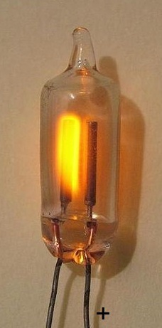
T in seconds. Put a 1 MΩ resistor, a 100 nF capacitor and a garden-variety NE-2 (Vs ≈ 90 V,
Vm ≈ 60 V) on a 120 V rail and the lamp winks at you a dozen-odd times a second (about
14 Hz — Vol 15 works the arithmetic) — no transistor, no IC, no logic, just gas obeying
its hysteresis. From there, cross-couple two
such branches through a shared capacitor and you get the classic two-lamp alternating flasher:
lighting one lamp shoves a step of charge through the coupling capacitor onto the other lamp’s
node, and the two trade the glow back and forth. That hand-off — one lamp firing and thereby
priming its neighbour — is, in embryo, exactly the glow-transfer mechanism that Vol 4 turns
into a ring.
12.2 Luc Small’s modern IN-3 ring counter
If Vol 4 is the theory of the ring counter, Luc Small’s 2016 build is the theory made
flesh with real, imperfect, twenty-first-century surplus parts, and it is the direct ancestor
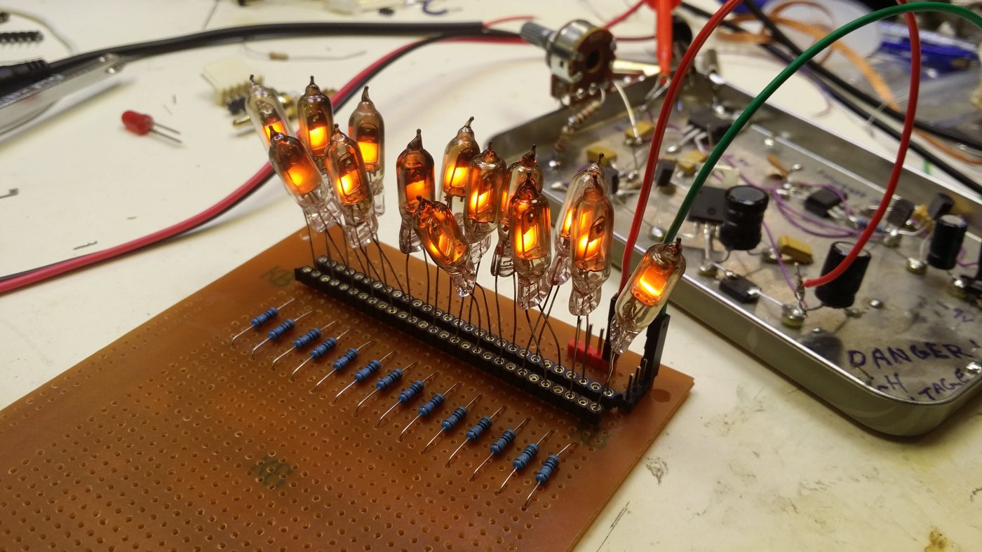
of the reference design in Vol 13. Small bought two hundred Russian IN-3 indicator neons
from Ukraine, discovered — as anyone will — that their striking and maintaining voltages were
scattered all over the map, and did the un-glamorous work the physics demands: a 48-hour
burn-in to let the gas chemistry settle, followed by a characterisation of fifty lamps that
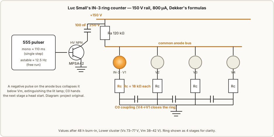
sorted them into three voltage clusters. The Lower cluster (14 lamps, Vs ≈ 73–77 V,
Vm ≈ 38–42 V) became the working ring. On a stiff 150 V rail he aimed for a per-lamp
current of 800 µA, which, feeding Ronald Dekker’s design equations, gives a cathode
resistor Rc of 18 kΩ (the arithmetic wants 16 875 Ω) and a common anode resistor Ra
of 120 kΩ (calculated 120 625 Ω). The stages are knitted into a ring by small coupling
capacitors, and the whole thing is stepped by a pulse driven onto the common anode through a
100 nF / 250 V capacitor and an MPSA42 high-voltage transistor. The transistor is the
only silicon in the counting path, and it is there only to yank the anode bus cleanly below Vm
so the lit lamp extinguishes and the coupling capacitors can hand the glow to the next stage.
The theory of operation is pure Vol 4. Exactly one lamp is lit; its cathode current develops a
transfer bias across its Rc that pre-charges the coupling capacitor to the next lamp’s
cathode. When the pulse collapses the anode, every lamp goes dark for an instant, but as the
anode recovers the pre-biased next stage reaches Vs first and lights — the dot has advanced
one seat, always in the same direction. What makes Small’s write-up the practical companion to
Dekker’s is the pulser: a pair of 555 timers, one wired as a monostable giving a ≈110 ms
one-shot so you can single-step the ring by hand and watch each transfer, the other as an
astable at ≈12.5 Hz so you can let it run and see the dot chase itself around the ring.
12.3 Ronald Dekker’s ring counter and the ZA1002 switching tube
Where Small worked with a bag of surplus indicator lamps, Ronald Dekker’s ring-counter
pages approach the problem from the theory side — but the physical ring he built to prove it
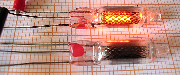
runs on much the same thing Small used: cheap, ordinary “drop-shaped” neon lamps, bought
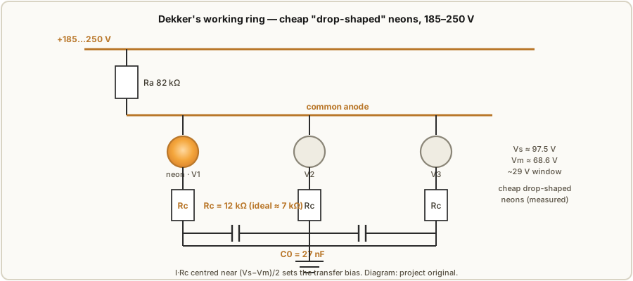
locally and measured. His batch came in at Vs ≈ 97.5 V (93.7–101.4 V) and Vm ≈ 68.6 V
(66.4–72.0 V), for a hysteresis window of about 29 V — not the luxurious window of a purpose-
built switching tube, but noticeably wider and far more consistent than a typical NE-2, and quite
enough to count reliably once binned. Dekker’s ten-stage ring runs on a 185–250 V supply with
Ra = 82 kΩ, Rc = 12 kΩ (a touch higher than the ideal ≈7 kΩ, deliberately), and
coupling capacitors C0 = 27 nF — the same common-anode, cathode-transfer-bias topology as
Small’s. Driven gently through capacitive coupling it is a sub-kilohertz device; driven hard with
TTL pulses through a high-voltage transistor that yanks the anode node down, Dekker pushed the
same ring to around 500 kHz (Vol 4).
Dekker’s other gift to this series is what happened when he did reach for the tube that was
supposedly designed for the job: the Philips ZA1002 cold-cathode switching tube. On paper it is
everything you want — Vs ≈ 170 V (a batch measured 169.1–171.0 V) and Vm ≈ 105 V (104.8–105.2 V),
a ≈60 V window three to five times wider than an NE-2’s, with a tritium priming source sealed
inside so it strikes in under a millisecond without waiting in the dark for a stray ion. But it was a
separate experiment, and it failed — for a reason that is pure physics. Tritium’s half-life is
12.3 years; a ZA1002 made around 1961 has now been through roughly five half-lives, leaving only
a few percent — of order 1/32, and by Dekker’s own reckoning as little as 1/64 — of its
original priming. Dekker documents exactly the consequence: aged NOS ZA1002s strike erratically
anywhere from 170 V up to 220 V, their once-tidy Vs smeared out by the loss of priming, and the ring
would not run reliably. The wide-window switching tube should be the right choice — but sixty years
of a ticking tritium clock means the humble drop-shaped neon, binned and burned-in, is what actually
counted.
12.4 The PA3FWM neon-logic clock — the showpiece
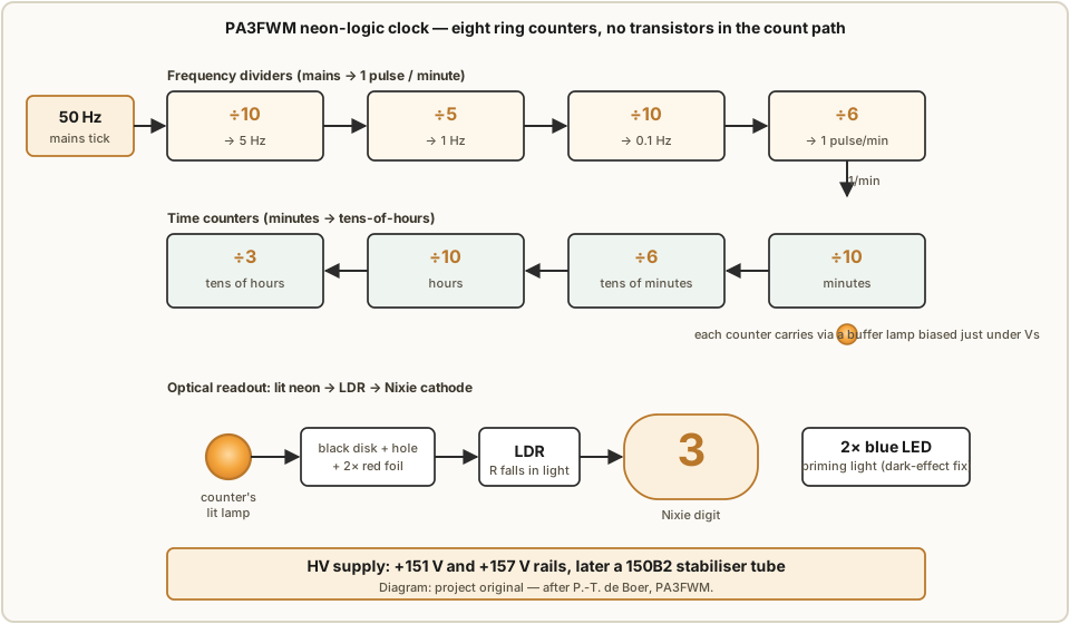
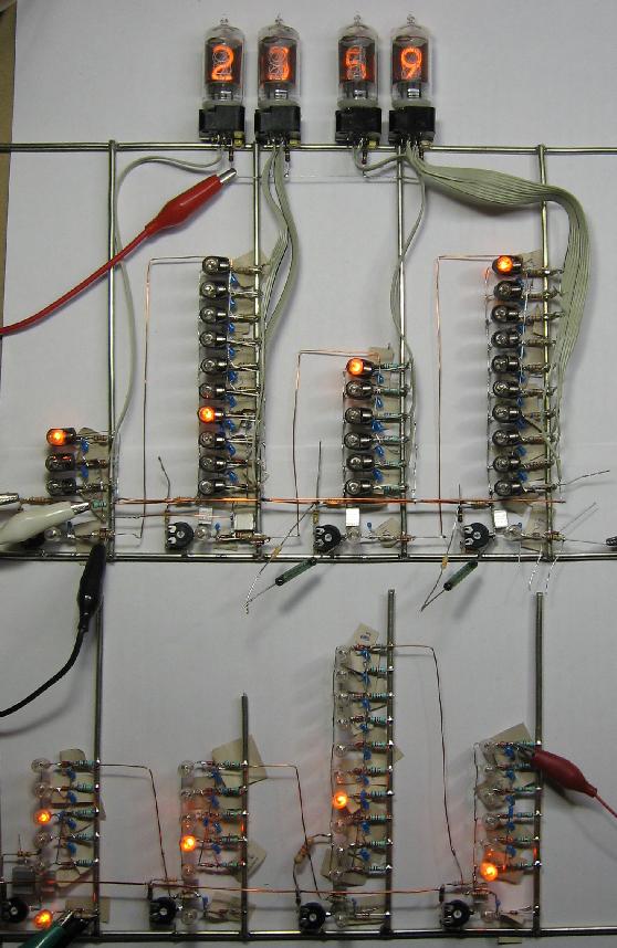
The centrepiece of this gallery, and the reason Vol 7 spends so long on drift, is Pieter-Tjerk de Boer’s (PA3FWM) clock built from neon lamps used as logic elements — arguably the most complete modern demonstration that you can keep time in nothing but glowing gas. Following the spirit of Dance’s 1967 chapter on neon logic, de Boer built the entire count path from cold-cathode ring counters, with not a transistor in the timekeeping itself. Eight ring counters do all the work. Four are frequency dividers that chew the 50 Hz mains down to a once-a-minute tick: a ÷10 stage (50 Hz → 5 Hz), a ÷5 (→ 1 Hz), another ÷10 (→ 0.1 Hz) and a ÷6 (→ one pulse per minute). The remaining four are time counters that accumulate the minutes and hours: ÷10 for minutes, ÷6 for tens of minutes, ÷10 for hours and ÷3 for tens of hours. Each ring’s lit stage is the digit, in exactly the way the WITCH computer’s dekatrons hold a number (§12.6) — the difference is that de Boer’s rings are built from discrete indicator lamps rather than integrated dekatron tubes.
Getting the count out to a readable display is where the build turns delightfully strange. A lit neon can’t drive a nixie tube directly, so de Boer reads each lamp optically: a lit stage shines onto a light-dependent resistor (LDR), whose resistance drops and pulls the corresponding nixie cathode down to the negative rail, lighting that numeral. Between lamp and LDR sits a hand-made optical attenuator — a black cardboard disk with a small hole and two layers of red foil — that blocks stray ambient light while passing the neon’s own orange-red glow. The rails run at +151 V and +157 V (the small offset later tidied up by swapping the neon voltage references for a proper 150B2 stabiliser tube). And because a ring built from weak modern lamps can’t reliably shove a carry pulse into the next ring, de Boer added an extra neon “buffer” lamp per counter, biased to just below its striking voltage, so that a small carry pulse tips it over strike and it delivers a clean, punchy pulse onward.
There is one more twist that earns this build its place as Vol 7’s cautionary spine. Neon
lamps suffer the dark effect — they strike late and erratically in the absence of light —
so a clock sitting in a dark room simply stops working. De Boer’s fix is charming and
pragmatic: two blue LEDs left permanently glowing inside the case to prime the lamps.
And yet, for all this care — burn-in, selection, buffering, priming, a stabilised supply —
the clock did not last. Individual lamps drifted in ways that Vs and Vm alone had not
predicted; buffers became unreliable, some stages failed only at certain count rates, and
after one to two years the accumulated ageing rendered the clock unusable. De Boer’s own
conclusion is the single most valuable sentence in this whole field: fully characterising a
neon lamp takes more than just its striking and maintaining voltages. It is a humble,
honest, and genuinely useful failure — the reason binning, burn-in and a stiff supply are
necessary but, on their own, not quite sufficient.
12.5 Dekatron scalers and counters
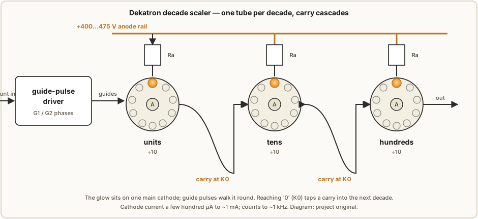
Everything so far has built a ring out of separate lamps. The dekatron — the subject of Vol 5 — does the opposite: it packs an entire ten-stage ring into a single glass envelope. A central disc anode faces a ring of ten main cathodes, and between each pair of main cathodes sit one or two guide cathodes. The glow rests on one main cathode; pulse the guides in the right order and the discharge is dragged one seat around the ring, so a single tube counts 0 through 9 as a visible orange dot spinning behind a numbered dial, with a carry tap that fires once per revolution to clock the next decade. Double-pulse (two-guide) dekatrons such as the GC10 family need a two-phase guide waveform; single-pulse types get by with one guide set and internal biasing; and separate selector dekatrons (the GS10 family) run heavier cathode current so their output can switch something, not merely display. A typical scaler runs the anode at +400–475 V through an anode resistor, with cathode currents from a few hundred µA up to about a milliamp, counting comfortably to ~1 kHz. Cascade three tubes and you have a 0–999 scaler; the carry from the units tube at its “0” cathode steps the tens tube, whose carry steps the hundreds tube — the same divide-and-carry logic as the neon ring, just integrated.
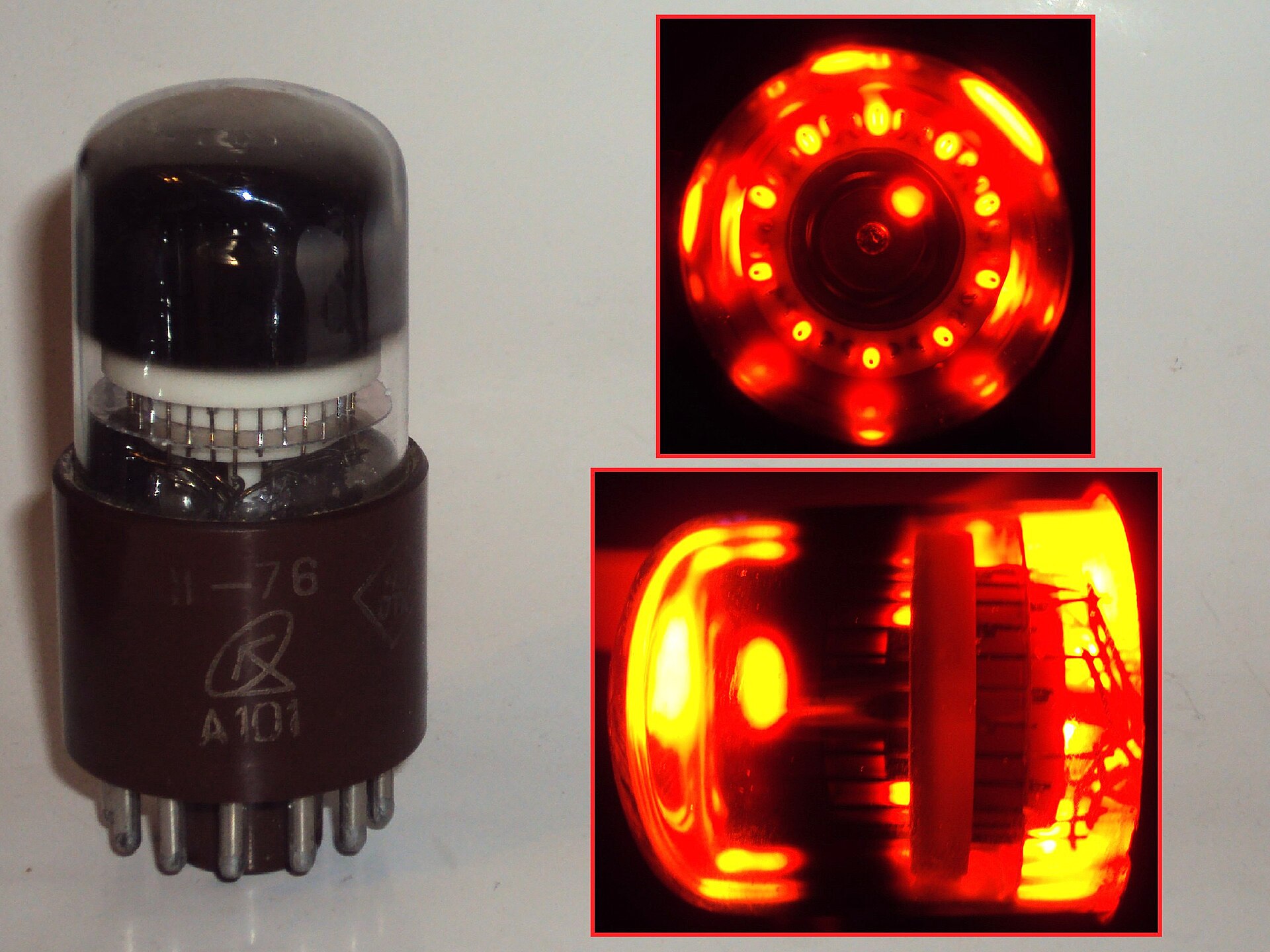
The dekatron is also the most watchable device in this series — its whole reason for existing is that you can see the count as a moving dot — which makes it the star of countless physics scalers, dose-rate meters, and event counters from the 1950s and 60s, and a perennial favourite of modern clock builders who drive four of them as seconds and minutes.

12.6 The Harwell WITCH — dekatrons as memory
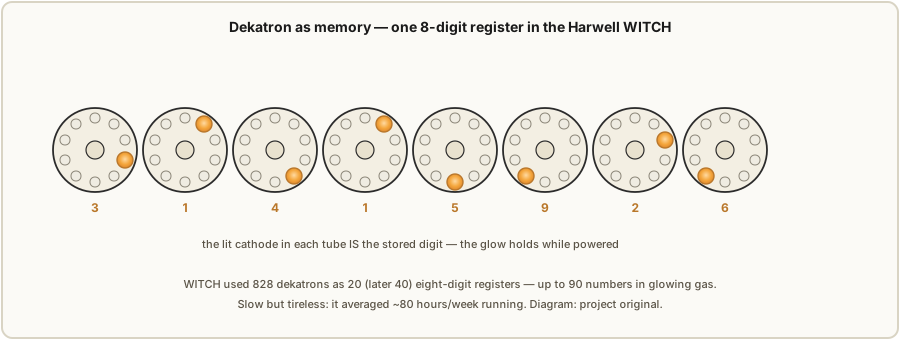
The most audacious use of the glow-transfer tube was not to count with it but to remember with it. The Harwell Dekatron Computer — later nicknamed the WITCH — used dekatrons not as a display but as its main memory. Because a dekatron holds its glow indefinitely on whichever cathode it was last stepped to, a single tube stores one decimal digit simply by where the dot is sitting; a row of eight tubes stores an eight-digit number, and the glow persists for as long as the anode rail is up. The machine used 828 dekatrons organised as 20 (later 40) eight-digit registers, giving it room to hold up to 90 numbers — a RAM built entirely from glowing gas, its contents literally visible to anyone standing in front of it. Sequencing was handled by 480 relays and the arithmetic by a couple of hundred valves, but the memory — the part that had to hold state reliably for hours — was cold-cathode, precisely because a dekatron is patient and undemanding: it draws little current and never forgets while powered.
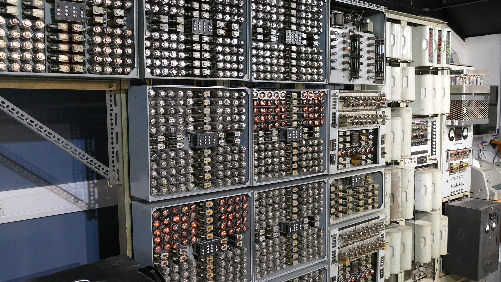
The WITCH was gloriously, deliberately slow — a multiplication took 5 to 10 seconds — but it was built for endurance rather than speed, and it delivered: through 1952–53 it averaged about 80 hours per week of running time, tireless where a human computer would tire. Built from 1949 and operational by 1951, it was restored and switched back on in 2012 and now runs at The National Museum of Computing at Bletchley Park, where it is recognised as the world’s oldest working digital computer — the clearest possible demonstration that a ring of glow discharge is not just a novelty but was, once, industrial-grade memory.
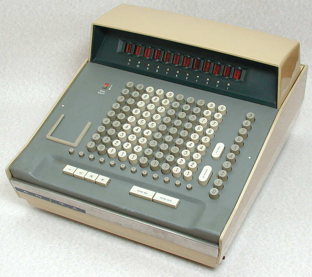
12.7 The Bell Punch ANITA calculator
If the WITCH proved cold-cathode tubes could remember, the Bell Punch / Sumlock ANITA proved they could go to market. Launched in 1961, ANITA (the Mark VII in Europe, the Mark VIII more widely) was the world’s first all-electronic desktop calculator — no motors, no gears, no moving parts beyond the keys, just a silent case full of cold-cathode tubes. Its registers and counting logic were built from gas-discharge tubes of the same family this series is about — dekatron-style counting tubes and cold-cathode trigger/switching tubes doing the add-and-carry — and its display was a set of numeric readout tubes glowing the answer. The appeal to a 1961 office was exactly the appeal of the neon ring in miniature: no mechanism to wear out, an instant silent answer, and a digit you could read as a lit numeral rather than a printed wheel. It sold well enough to make Bell Punch the UK’s largest calculator supplier for a decade, until the same silicon that ended every other story in this gallery caught up. For our purposes ANITA is the commercial proof point: the cold-cathode counting tube was not a museum curiosity but a shipping consumer product, and for a few years in the early 1960s the fastest way to add a column of numbers in an office was to watch gas glow.
12.8 The Philips Philicorda organ — neon octave dividers
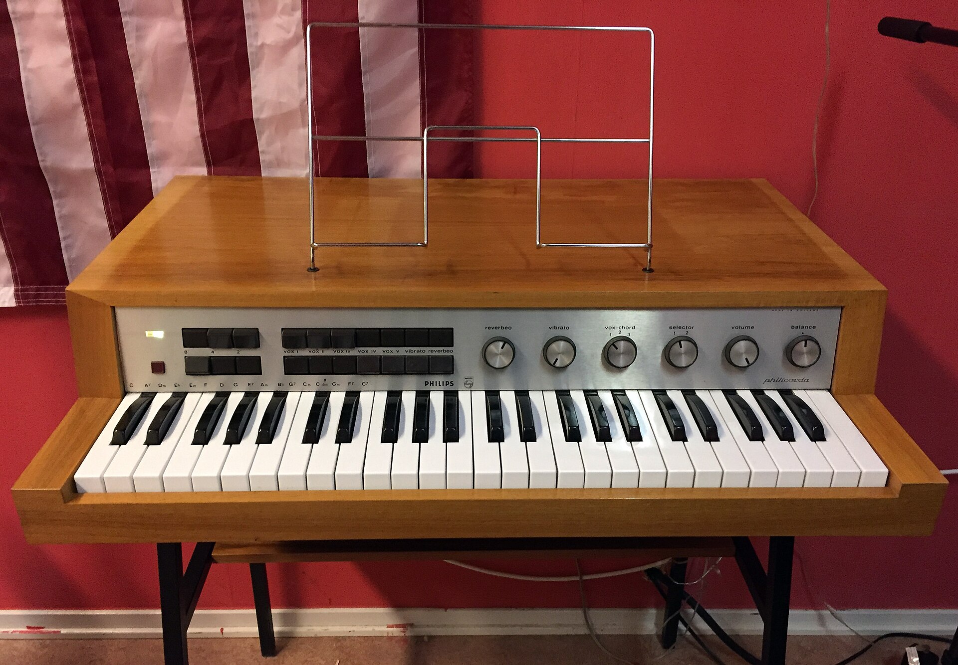
The one place the neon divider went truly mainstream was, of all things, a musical instrument. The early all-tube Philips Philicorda electronic organs (the AG7400 of 1961 and the AG7500 of 1963) generated their notes with neon-based octave dividers — cold-cathode tubes of the ZA1001 switching-tube family doing exactly the frequency division of Vol 6. The architecture is the natural application of a counting divider: rather than build a separate oscillator for all sixty-odd notes, the Philicorda used twelve Hartley LC oscillators, one per semitone, each tuned to a note in the top octave, and then divided each of those down the keyboard with a chain of neon ÷2 stages. Each ÷2 is a neon bistable clocked by the stage above it, and because a counting divider produces exactly one output cycle per two input cycles, every division is a perfect octave — the pitch of every low note is locked rigidly to its top-octave master oscillator, with no drift of its own added by the neon stages.
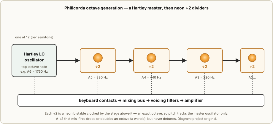
This is the practical illustration of Vol 6’s subtle accuracy point. The neon dividers add no
pitch error — an octave is an octave to the integer — so the instrument’s tuning stability is
entirely a property of its twelve master oscillators. What the neon stages can do is
misbehave in reliability: a tired divider that occasionally drops or doubles a transfer
produces an octave glitch — a momentary warble or dropout in a note — rather than a note that
drifts flat. That failure signature is audible and characteristic, and it is a large part of
why the Philicorda has the “warm, faintly unstable” voice its enthusiasts prize. The full
treatment of this instrument, its ZA1001 tubes, and its restoration lives in the sibling
project ../Philicorda/, cross-referenced from Vol 6; here it stands as the marquee
application of neon frequency division.
12.9 NE-2 memory, latches and neon-logic gadgets
Between the flasher of §12.1 and the systems above lies a whole zoo of small neon-logic
gadgets, and they are worth a case of their own because they are the most buildable items in
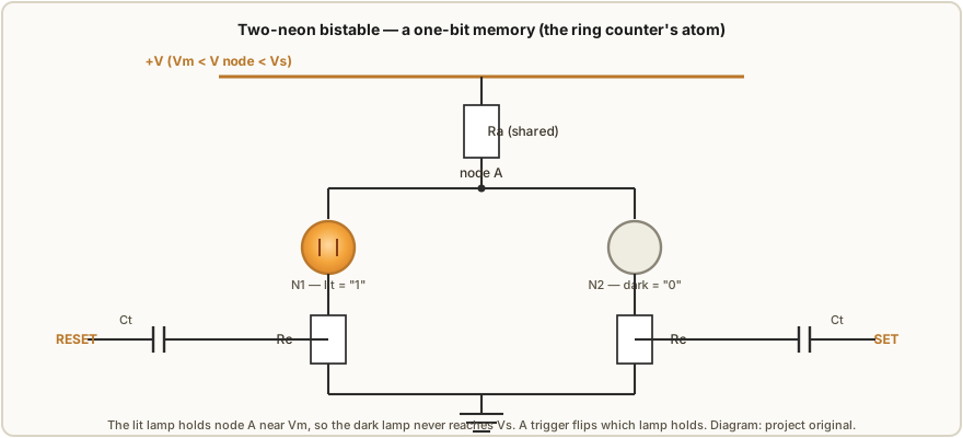
this gallery. The key insight is that a neon lamp on a rail biased between Vm and Vs is a
one-bit memory: once struck it stays lit, once extinguished it stays dark, and only a
deliberate pulse changes its state. Wire two lamps to share a common anode resistor and you
get a bistable — a neon flip-flop. The lit lamp holds the shared anode node down near Vm,
which keeps the dark lamp starved below its Vs; a “set” pulse coupled into one cathode fires
that lamp and steals the anode, extinguishing the other, and the pair latches in the new state.
That single cell is the atom of everything in this volume: chain a row of these couplings into a
loop and you have the ring counter of §12.2; integrate ten of them in one envelope and you have
the dekatron of §12.5; use one as a store and you have a bit of the WITCH’s memory.
From this cell hobbyists have built neon shift registers, neon “dice,” Nim and tic-tac-toe machines, and — the example de Boer himself cites — the neon ring-counter “calculator” featured in Electronics Illustrated, November 1966, a construction article that put the glow-transfer counter into the hands of home experimenters a decade before the pocket calculator. These gadgets share the ring counter’s whole personality: they are cheap, they are visible, they are marginal, and they reward exactly the binning-and-biasing discipline this series preaches. They are also the ideal place to start building, which is why Vol 13’s reference project is essentially a well-documented, carefully-binned version of the same idea.
FIGURE SLOT 12.9a — A scan of the Electronics Illustrated, November 1966 neon ring-counter “calculator” construction article (title page or schematic). Source: an archive.org magazine scan or a vintage-electronics collection. FIGURE SLOT 12.9b — A hobbyist neon-logic gadget in operation — a neon “dice,” Nim machine, or shift register — lamps glowing. Source: a maker blog or Hackaday (credit verbatim). FIGURE SLOT 12.9c — A neon bistable / flip-flop built on a breadboard, one lamp lit, to match Figure 12.9. Source: an original bench photo on the reference build, or a project page.
12.10 Art, sculpture and display uses
Not every use of a neon ring is trying to be useful, and the technology’s sheer beauty has made it a favourite of artists and display builders — a legitimate application in its own right, because “make people stop and look” is a real design goal. The same properties that make a dekatron a good counter make it a mesmerising kinetic object: a warm orange dot that moves, that you can watch keep time, with none of the flat glare of an LED. Modern makers build dekatron clocks precisely for the spectacle of the spinning dot; others arrange neon indicator lamps into large slow-scanning rings, “larson scanners,” and glowing sculptures that use the relaxation oscillator of §12.1 as a rhythmic light source. The aesthetic lineage runs straight from the pilot-lamp NE-2 to nixie and dekatron art, and it is arguably where the craft is most alive today: silicon long ago won the argument about counting, but it never won the argument about looking good doing it.
FIGURE SLOT 12.10a — An artful dekatron or nixie-and-dekatron clock as an object, styled/lit for display. Source: a maker or artist portfolio (credit verbatim). FIGURE SLOT 12.10b — A neon-lamp light sculpture or slow-scanning ring installation, glowing in a darkened room. Source: an artist’s site or a Hackaday feature.
12.11 What the gallery teaches
Step back from the individual exhibits and three threads run through all of them. The first is
that it is all one circuit. The relaxation oscillator, the two-lamp flasher, the bistable
latch, the ring counter, the dekatron, the WITCH’s memory, the Philicorda’s ÷2 stage — every
one is the same Vs/Vm hysteresis of Vol 2 arranged so that firing one discharge biases the
next. The only things that change from a 90 V flasher to a 475 V dekatron scaler are the tube’s
hysteresis window, the rail voltage, and how many cells are wired together. Learn the atom of
§12.9 and you have, in principle, understood the whole room.
The second thread is that the tube’s margin decides everything. Small’s cheap IN-3s needed a
48-hour burn-in and a three-way sort before they would count at all; a fresh ZA1002, with its
fat 60 V window, would count almost carelessly — but sixty years on, decayed tritium priming
leaves even the “good” NOS tube striking erratically, which is exactly why Dekker’s ring actually
ran on binned drop-shaped neons rather than the premium switching tube. The wider the Vs − Vm window and
the fresher the priming, the less the surrounding circuit has to fight; the narrower the window,
the more the binning, the stiff supply, and the buffer lamps of Vol 7 are earning their keep.
Every exhibit in this gallery is, at bottom, a negotiation with that margin.
The third thread is the one de Boer’s clock states most honestly: glow discharge was never a toy. Dekatrons stored real numbers in a real computer that still runs; cold-cathode tubes added real columns of figures in real 1961 offices; neon dividers made real music in tens of thousands of organs. Silicon replaced all of it because silicon is cheaper, cooler and lower-voltage — not because the glow ever stopped working. What the gallery finally teaches is that the neon ring counter sits at a rare intersection: a technology that was once industrial-grade, is now beautiful, and remains, for the patient maker with a binned box of lamps and a stiff high-voltage rail, entirely buildable. Vol 13 builds it.
References
- R. Dekker, “A Neon Ring Counter” / Ring Counter Variations — https://www.dos4ever.com/ring/ring.html (ZA1002 measured Vs/Vm, the 82 kΩ / 12 kΩ / 27 nF ring, the tritium-decay ageing data, design equations).
- L. Small, “Neon Ring Counters” (2016-10-08) — https://lucsmall.com/2016/10/08/neon-ring-counters/ (200× IN-3, 48 h burn-in, the three clusters, 150 V / 800 µA / 18 kΩ / 120 kΩ / 100 nF, the 555 mono/astable pulser, the MPSA42).
- P.-T. de Boer (PA3FWM), “A clock using neon lamps as logic elements” — https://www.pa3fwm.nl/projects/neonclock/ (the eight ring counters, ÷10/÷5/÷10/÷6 and ÷10/÷6/÷10/÷3, LDR-to-nixie display, +151/+157 V, 150B2, buffer lamps, the ageing failure story, the Electronics Illustrated Nov 1966 citation).
- J. B. Dance, Electronic Counting Circuits (London: Iliffe / New York: American Elsevier, 1967) — in the site’s reference library (neon logic, dekatrons, the canonical treatment).
- “Harwell computer” (Harwell Dekatron / WITCH) — en.wikipedia.org/wiki/Harwell_computer; The National Museum of Computing (828 dekatrons, 20/40 eight-digit registers, ~80 hours/week, restored 2012).
- “Philicorda” — en.wikipedia.org/wiki/Philicorda; radiomuseum.org philips_philicorda_ag7500; and the sibling project
../Philicorda/(twelve Hartley oscillators, neon ZA1001 octave dividers, AG7400/AG7500). - Bell Punch / Sumlock ANITA (1961, first all-electronic desktop calculator) — anita-calculators.info “The Technology Explained”; vintagecalculators.com “Cold-Cathode Tube & Dekatron”.
- Dekatron family and operating data — Ericsson Telephones Ltd, Tube Technical Handbook (1964); tube-tester.com dekatron archive; microbasement.com GC10B page.
- Manley & Buckley, “Neon Ring Counter,” Electronics, January 1950 — the original ring-counter paper (via Dance).
Comments (0)