Neon Ring Counters · Volume 11
The Burn-In / Ageing Jig — Build It
A current-limited socket bank that conditions and sorts a box of raw neons, plus the measure-and-bin station that turns them into design data
A bag of new indicator neons is not a bag of components — it is a bag of candidates. Straight from the factory or the surplus bin, each little NE-2 or IN-3 has a striking voltage and a maintaining voltage that are still moving, and moving fastest in the very first hours of operation, so any number you measure on a fresh lamp is a number that will have quietly changed by the time you have soldered the ring together. Worse, a fraction of the lamps are simply bad — they will strike erratically, glow unevenly, flicker, or fail outright — and you would very much rather discover that on a bench jig running twenty of them at once than in a finished counter where one weak stage stalls the whole marching dot. The cure is old, dull, and completely non-negotiable: run every lamp at its rated current for a day or two before you trust it, then and only then measure it and sort it into a bin. This volume builds the box that does the running, and the little station that does the measuring and sorting. It is the least glamorous hardware in the whole series and the single biggest predictor of whether your ring counter works — Vol 1’s decision tree said do not skip the binning, and this is the volume where you earn that binning honestly.
⚠ The jig runs a ~150 V DC rail behind a reservoir capacitor that stays charged after you switch off; that is enough to hurt or kill, and the socket field is all live at once. Treat every rail here as lethal until a meter proves it discharged. The full discipline — the single-hand rule, the bleeder, the discharge tool — is Vol 14, and it applies to a burn-in jig exactly as much as to a finished counter.
11.1 Why burn-in is mandatory
The physics behind the ritual is the same gas cleanup that Vol 7 named as the largest
single source of drift in a cold-cathode lamp. A sealed neon envelope is never perfectly
clean: the electrodes carry adsorbed gases and surface contamination, and the fill gas
itself interacts with the cathode surface. When the lamp first runs, the discharge scours
the cathode, sputters a little material about, and drives adsorbed impurities out of and
into the metal until a rough equilibrium is reached. Every one of those changes moves the
breakdown condition, which is to say it moves Vs, and to a lesser extent Vm. The change
is not linear in time — it is front-loaded. As Ronald Dekker put it after ageing his own
tubes, the largest change in parameters occurred during the first few hours. Run a lamp
for its first afternoon and you have absorbed the bulk of the lifetime shift; leave it raw
and that shift happens inside your finished circuit, pulling the carefully centred bias
of Vol 4 off centre exactly when you can least afford it.
There is a second, blunter reason, and it is about mortality rather than drift. Electronic parts fail on a bathtub curve — a burst of infant mortality in the first hours, a long flat plateau, then wear-out — and cold-cathode lamps are no exception. A burn-in run is a deliberate infant-mortality screen: the lamps that were going to die young die on the jig, in front of you, harmlessly, and you throw them away before they ever get a bin number or a place in a ring. A lamp that has glowed steadily for 48 hours at rated current has proven something a fresh lamp cannot.
How long, and at what current? The two modern builders this series leans on landed in the
same place from different directions. Luc Small burned in his 200-odd Russian IN-3s for
48 hours each on a fixture of fourteen sockets and a 150 V supply, cycling all fifty of
his characterisation sample through in batches over eight days, and then measured every one
before and after to quantify the shift rather than assume it. Ronald Dekker aged his
tubes for three days, running them on AC at roughly 1 mA per tube from a variac,
each with its own series resistor, and measured a sample of 21 tubes before and after:
average Vs and Vm both fell by about 1.5 V, the ~12 V gap between them holding
roughly constant — a small mean shift hiding much larger, non-uniform, sometimes
bidirectional changes in individual lamps. That non-uniformity is the whole point. You
cannot predict which way a given lamp will move, so you must age them all and then
re-measure them all; the burn-in does not tell you the answer, it makes the answer stop
changing long enough to be worth writing down. A day is a sensible floor, two days is
comfortable, and there is no penalty but electricity for going longer.
11.2 The design of a good jig
A burn-in jig is almost embarrassingly simple — it is a high-voltage rail, a row of lamps, and a clock — but three design choices separate a jig that helps from one that lies to you.
11.2.1 A current-limited high-voltage rail
The rail wants to sit comfortably above the striking voltage of every lamp you might load,
so that even the highest-Vs tube in the batch lights reliably. For indicator neons whose
Vs tops out around 90–110 V, a 150 V rail is the natural choice — the same rail Luc
used, and the same rail Vol 9’s modern boost converter delivers, so the jig can borrow that
supply wholesale rather than inventing a new one. The rail must be current-limited, for
two reasons. First, a lamp can fail short — a fractured envelope, an internal arc — and a
stiff unlimited supply behind such a fault will dump its full reservoir into the fault,
melting a resistor or worse. Second, current limiting is the cheapest insurance against your
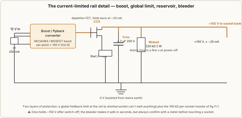
own fingers. Vol 9’s supply already carries a feedback set-point, a reservoir cap, a bleeder,
and (if you built the foldback option) a current limit; the jig adds a global fuse and leans
on the per-socket resistors below for the fine limiting. The rail detail is drawn in fig
11.2 — boost converter, a global foldback at about 25 mA, a 4.7 µF/250 V reservoir, and a
220 kΩ bleeder that drains it in a few seconds at switch-off.
11.2.2 A bank of sockets, each with its own series resistor
This is the one design rule that matters more than any other, and it is worth stating
baldly: every socket gets its own series resistor, and the lamps never share one. If you
paralleled a dozen lamps onto a single current-limiting resistor, the negative-resistance
character of the glow discharge (Vol 2) would let the lamp with the lowest Vs hog the
current and the rest would sit dark or flicker — and one lamp failing short would collapse
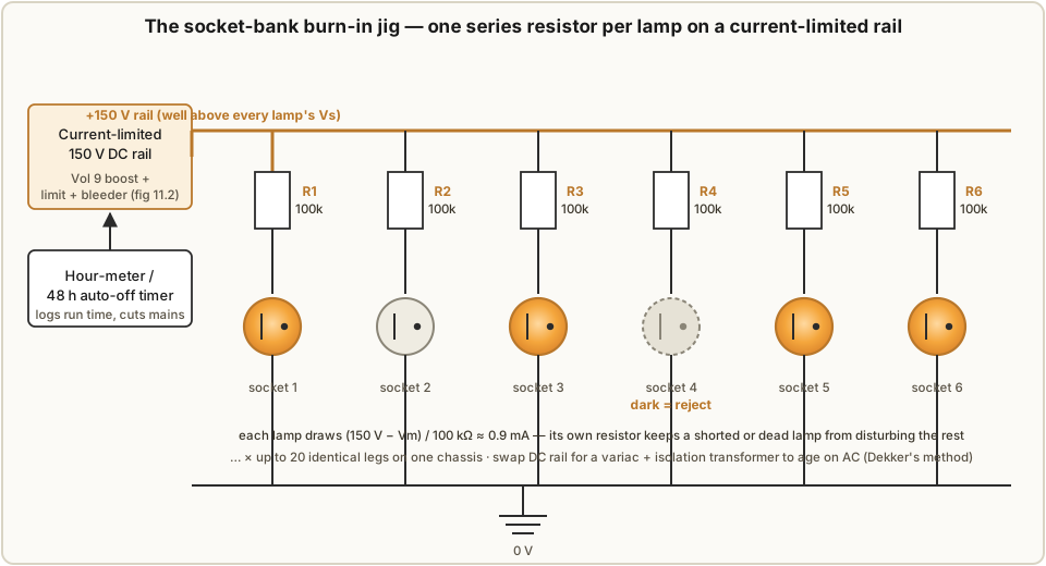
the shared node and extinguish the whole bank. Give each lamp its own resistor and each leg
is an independent, self-limited relaxation circuit that neither knows nor cares what its
neighbours are doing. A shorted lamp takes out only its own leg; a dead-open lamp simply
leaves its socket dark; a low-Vs lamp draws its own modest current and no more. This is
exactly how both Dekker and Luc built their fixtures — Luc’s fourteen sockets each behind
one of fourteen series resistors — and it is the topology of fig 11.1.
Sizing the series resistor is the relaxation-oscillator arithmetic of Vol 2 run backwards.
You want each lamp near its rated operating current — call it Iburn ≈ 0.9 mA, comfortably
inside the ~0.8–1 mA both builders used — with the rail Vrail = 150 V and the lamp sitting
at its maintaining drop Vm ≈ 55 V once lit:
Rseries = (Vrail − Vm) / Iburn = (150 V − 55 V) / 0.9 mA ≈ 106 kΩ → use 100 kΩ.A standard 100 kΩ resistor gives about (150 V − 55 V) / 100 kΩ ≈ 0.95 mA, and since
you have not yet measured Vm (that comes after burn-in), the exact value hardly matters —
anywhere from 0.7 mA to 1 mA conditions the lamp perfectly well. The dissipation is trivial:
P = Iburn² · Rseries = (0.9 mA)² × 100 kΩ ≈ 0.08 W, so a common 0.5 W metal-film
resistor is loafing, and metal-film is the right pick for the low voltage coefficient Vol 10
argued for. The whole bank is Rseries repeated as many times as you have sockets; twenty is
a comfortable number for a single chassis.
11.2.3 AC or DC, and how much current
Both excitations condition a lamp; they differ in which electrode gets cleaned. On DC, one electrode is always the cathode and takes all the sputtering and cleanup — which is exactly right if you already know which electrode will be the cathode in service, since you age the lamp in the same orientation it will run. On AC — Dekker’s choice, a variac through an isolation transformer giving an adjustable 0–180 V, each lamp again behind its own series resistor — both electrodes spend half the cycle as the cathode, so both get conditioned symmetrically. For a near-symmetric indicator neon that is arguably the more thorough burn-in, and AC has the practical charm that a variac plus an isolation transformer is a supply many benches already own. The honest summary: DC if you will run the lamp DC and want to condition the working cathode; AC if you want to condition both electrodes or you simply have a variac handy. Either way the target is ~0.8–1 mA per lamp, the same current the lamp will see on the normal-glow plateau in service, so the burn-in exercises it under representative conditions rather than stressing it. The jig of fig 11.1 is drawn for DC off the Vol 9 rail; swapping the rail block for a variac-plus-isolation-transformer converts it to Dekker’s AC method with no other change, because the per-socket resistors do their job on either.
⚠ If you take the AC route, the isolation transformer is not optional — a bare variac shares a live connection with the mains and offers no isolation at all.
11.2.4 A timer or hour-meter
Burn-in is measured in tens of hours, far longer than anyone will stand and watch, so the jig needs to keep its own time and preferably switch itself off. Two cheap parts cover it: a panel hour-meter (a mechanical or digital run-time counter in the mains feed) that tells you how long the current batch has actually accumulated, and a timer that cuts the mains after a set interval — a mechanical time-switch or a small relay-and-timer will end a 48 h run unattended so the jig is not left live for a week because you forgot it. Both are wired on the low-voltage mains side, well away from the HV rail, and both appear in the layout of fig 11.5. Logging the hours matters because the whole premise is that most of the shift happens early: a lamp with 6 hours on it is only partly conditioned; one with 48 is done.
11.2.5 Optional per-socket current indication
You do not strictly need to know each lamp’s current during burn-in — a lit socket is drawing
roughly the design current by construction, and a dark socket is the only diagnosis that
matters, since it means an open lamp, a bad contact, or an early death, all of which say
“reject.” The glow is its own indicator, and scanning the bank for dark sockets is the whole
inspection. If you want a number, the tidy trick is a single shared meter brought to any
socket on demand: a rotary switch selects one socket’s series resistor, and a shared
microammeter (or a DMM on its µA range) reads the current in that leg, since I = ΔV / Rseries across a known resistor. One meter, one switch, twenty sockets — no per-socket
instrument, no clutter. That shared-check arrangement is the small rotary-switch-plus-meter
block in the layout sketch.
11.3 The full schematic and the rail
Put the two schematics together and the jig is complete. Figure 11.2 is the rail: 12 V in, a boost converter set to 150 V, a foldback current limit, a reservoir capacitor, and a bleeder — the modern supply of Vol 9 with its protection features made explicit. Figure 11.3 is the load: that 150 V rail across the top, a ground bus along the bottom, and between them a row of identical legs, each a 100 kΩ series resistor feeding one socketed lamp. The hour-meter and auto-off timer sit in the mains feed to the rail. Nothing about the circuit is subtle; its whole virtue is in the repetition and the isolation — twenty independent little glow circuits sharing one clean rail and one clock.
11.4 Physical layout
The mechanical arrangement wants three things: the lamps grouped where you can scan them all at a glance, the high voltage guarded from fingers, and the instruments on a front panel. A shallow aluminium chassis carries a strip-board sub-panel drilled for a grid of pin sockets — four rows of five gives the twenty legs above — with each 100 kΩ resistor tucked underneath its socket. The current-limited supply module, the hour-meter, the auto-off timer, and the optional select-switch-and-µA-meter live along one end of the panel; the mains inlet and switch sit at a corner. Critically, a perforated guard lid covers the socket field whenever the rail is live, so that a live 150 V bank is never open to a stray hand — the lamps show through the perforations, so you keep the at-a-glance inspection without keeping the hazard. The layout is sketched in fig 11.5.
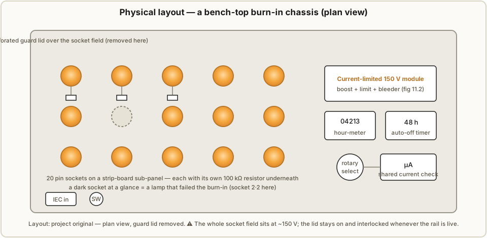
FIGURE SLOT (pending) — The finished socket bank: the strip-board sub-panel with its grid of pin sockets and the row of series resistors soldered beneath, before the guard lid goes on.
11.5 Bill of materials
The jig is deliberately cheap; the only part worth spending on is the supply, and Vol 9 already built that. Quantities assume a twenty-socket bank.
Table 1 — 11.5 Bill of materials
| Ref | Part | Value / spec | Qty | Notes |
|---|---|---|---|---|
| — | Current-limited HV supply | 12 V in → 150 V out, ~25 mA, foldback + bleeder | 1 | Built in Vol 9; or an off-the-shelf nixie boost module |
| Cres | Reservoir capacitor | 4.7 µF / 250 V film or electrolytic | 1 | Part of the supply; rate ≥ 250 V |
| Rbleed | Bleeder resistor | 220 kΩ / 2 W | 1 | Drains Cres in a few seconds at switch-off |
| R1–R20 | Per-socket series resistors | 100 kΩ / 0.5 W metal-film, 1 % | 20 | One per socket; metal-film for low VCR (Vol 10) |
| — | Pin sockets / turned-pin strip | to suit NE-2 / IN-3 leads | 20 | Or a ZIF strip for tool-free swapping |
| — | Hour-meter | mains 6-digit run-time counter | 1 | Logs accumulated burn-in time |
| — | Auto-off timer | mechanical time-switch or relay+timer | 1 | Cuts mains after the set interval |
| SW1 | Rotary select switch | 1-pole, 20-way | 1 | Optional — routes the shared µA meter per socket |
| M1 | Microammeter / DMM | 0–1 mA range | 1 | Optional — per-socket current check |
| — | Chassis + perforated guard lid | aluminium, bench-top | 1 | Guard lid interlocked over the live socket field |
| — | IEC inlet, switch, fuse | 250 mA on the LV side | 1 set | Mains entry |
| — | (AC option) variac + isolation transformer | 0–180 V, isolated | 1 | Replaces the DC rail for Dekker-style AC ageing |
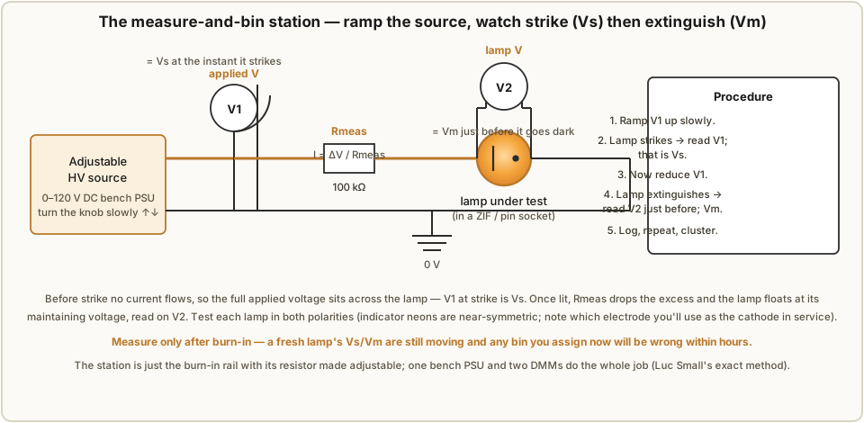
11.6 The measure-and-bin station
Burn-in conditions the lamps; it does not tell you what they became. For that you need to
measure each lamp’s Vs and Vm after it comes off the jig, and the station that does it is
nothing more than one socket of the burn-in jig with its supply made adjustable and two meters
watching. Luc built exactly this: a bench supply he could ramp, one voltmeter on the supply
and one across the lamp, and a spreadsheet. Figure 11.5 is the circuit.
11.6.1 Ramping for Vs and Vm
The measurement exploits a small, elegant fact. Before the lamp strikes, no current flows, so there is no drop across the series resistor and the entire applied voltage appears across the lamp — which means the supply voltage at the instant of breakdown is the striking voltage. So the procedure is:
- Start the adjustable source low — comfortably below any lamp’s
Vs, so around 65 V for this batch whose lowest cluster does not strike until ~73 V — and turn it up slowly. - The instant the lamp strikes — a sudden orange glow — read the source voltmeter V1. That is
Vs. - Now the lamp is lit and current flows; the series resistor drops the excess and the lamp settles to its maintaining voltage, read directly on V2 across the lamp.
- Reduce the source slowly. Watch V2; at the point where the glow extinguishes, the lamp
voltage just before it went dark is the maintaining voltage
Vm. - Record
Vs,Vm, and — if you like — the operating currentI = ΔV / Rseriesfrom the drop across the measuring resistor. Repeat in the reverse polarity: indicator neons are nearly symmetric, but note which electrode you intend to use as the cathode in service and record that orientation’s numbers.
The station is the burn-in leg with Rseries kept (100 kΩ works fine as the measuring
resistor too) and the fixed rail swapped for an adjustable 0–120 V bench supply. One supply,
two DMMs, one socket. Measure only after burn-in — running the ramp on a fresh lamp gives
you a Vs that will be a volt or two different tomorrow, and a bin assigned on that number is
a bin you will regret.
11.6.2 A data-logging template
Sorting is only as good as the record, so log every lamp the same way. A spreadsheet with one row per lamp — give each a physical ID, a paper tag or a dot of paint — turns a box of identical-looking lamps into data you can cluster:
Table 2 — identical-looking lamps into data you can cluster
| Lamp ID | Vs before (V) | Vm before (V) | Vs after (V) | Vm after (V) | Vs−Vm (V) | Bin | Notes |
|---|---|---|---|---|---|---|---|
| 001 | 91 | 55 | 76 | 40 | 36 | Lower | steady glow |
| 002 | 88 | 54 | 84 | 44 | 40 | Middle | — |
| 003 | 95 | 57 | 90 | 51 | 39 | Upper | slow strike in dark |
| 004 | 86 | 52 | — | — | — | reject | flickered, then dark at 3 h |
| … |
The before columns are optional but instructive — they are how Luc and Dekker proved the
shift is real and non-uniform, and filling them in for a sample of a dozen lamps teaches you
more about your particular batch than any datasheet. The Vs−Vm column is the number the ring
design actually cares about, since it sets the transfer-bias margin of Vol 4.
11.6.3 Clustering into bins — the worked example
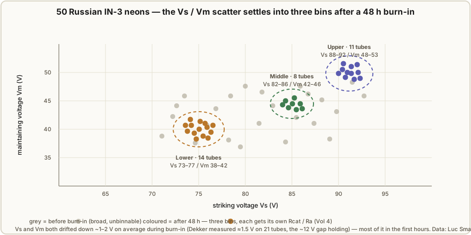
Plot the measured Vs against Vm for the whole batch and the sort does itself. Raw, the
points are a broad cloud with no obvious structure — which is precisely why you cannot design a
ring from an unsorted box. After burn-in, the same lamps settle into distinguishable
clusters, and each cluster becomes a bin of lamps alike enough to share one set of
resistor values. Luc’s fifty characterised IN-3s are the canonical example; the lamps that
grouped cleanly fell into three bins (the rest were outliers or rejects that never earned a
place in a ring):
Table 3 — place in a ring)
| Bin | Count | Vs range | Vm range | Vs−Vm window |
|---|---|---|---|---|
| Lower | 14 | 73–77 V | 38–42 V | ~35 V |
| Middle | 8 | 82–86 V | 42–46 V | ~40 V |
| Upper | 11 | 88–92 V | 48–53 V | ~40 V |
Figure 11.6 is that scatter: a grey, unbinnable cloud before burn-in and three tight, colour-coded clusters after. The clusters are not equal in size — the Lower bin is the largest here — and a ring needs all its stages from the same bin, so the biggest bin usually decides how long a ring you can actually build (fourteen Lower-bin lamps comfortably fill a ten-stage ring with spares; the eight Middle-bin lamps do not). This is the ordinary reality of surplus lamps, and it is why you buy far more than you need.
11.6.4 Handing the bins to the ring design
A bin is not the end — it is the input to Vol 4’s arithmetic. Each cluster’s average Vs and
Vm feed the cathode-resistor and anode-resistor formulas directly. Taking the Lower bin as
Luc did — average Vs ≈ 75 V, average Vm ≈ 40 V — and choosing an operating current Inom =
800 µA, the cathode resistor comes from centring the transfer bias at half the window,
Rcat = (Vs,avg − Vm,avg) / (2 · Inom),and the anode resistor from dropping the rail down to the lamp’s working voltage,
Ra = (Vsupply − Vlamp) / Inom,which for the Lower bin on a 150 V rail is where Luc’s built values — Rcat ≈ 18 kΩ, Ra
≈ 120 kΩ, coupling cap 100 nF / 250 V — come from (Vol 4 walks the full arithmetic and defines
every symbol). The essential point is the chain: burn-in stabilises the lamps → measurement
captures Vs/Vm → clustering groups the alike ones → the cluster averages set Rcat and Ra
for a ring built only from that bin. Skip any link and the ring inherits a spread its resistor
values were never designed for — the marginal ~12–20 V indicator-neon window (Vol 3) has no room
to absorb the difference, and the marching dot stalls or double-steps. A different bin simply
means a different pair of resistor values; the topology never changes, only the numbers on Rcat
and Ra do.
11.7 The workflow, start to finish
Put together, a batch of raw neons becomes a set of design-ready bins in six unhurried steps:
(1) load the socket bank and run it at ~0.9 mA per lamp for 24–48 hours, logging the hours;
(2) cull every socket that went dark or flickered — the infant-mortality screen; (3) move
each survivor to the ramp station and record Vs and Vm in the same orientation it will run;
(4) plot Vs against Vm and let the clusters emerge; (5) tag each lamp with its bin;
(6) hand the largest usable bin’s average Vs/Vm to Vol 4 and build the ring from that bin
alone. It is slow, it is dull, and it is the difference between a counter that runs for an
afternoon and one that runs for a year — the honest lesson of the PA3FWM clock (Vol 7) is that
even this is not always enough, but it is the necessary foundation everything else is built on.
Build the jig once and it serves every neon project you will ever attempt.
11.8 11.x References
- L. Small, “Neon Ring Counters” (2016-10-08) — https://lucsmall.com/2016/10/08/neon-ring-counters/ (the 48-hour 14-socket burn-in fixture, the ramp-up Vs/Vm measurement, and the three IN-3 clusters used as this volume’s worked example).
- R. Dekker (dos4ever), “A Neon Ring Counter” / Ring Counter Variations — https://www.dos4ever.com/ring/ring.html (three-day AC ageing at ~1 mA per tube via variac, the 21-tube before/after ~1.5 V shift, the “largest change in the first few hours,” and the Fig 10B Vs/Vm measurement method).
- J. B. Dance, Electronic Counting Circuits (London: Iliffe / New York: American Elsevier, 1967) — in the site’s reference library (cold-cathode conditioning and selection practice underlying both modern builds).
- Cross-references within this series: Vol 2 (relaxation-circuit sizing, negative resistance), Vol 3 (indicator-neon selection and the marginal window), Vol 4 (the
Rcat/Radesign equations the bins feed), Vol 7 (drift and gas-cleanup ageing), Vol 9 (the current-limited boost rail the jig reuses), Vol 10 (metal-film series resistors), and Vol 14 (the high-voltage safety discipline).
Comments (0)