Neon Ring Counters · Volume 10
Capacitors & Resistors — Choosing the Passives
Why the humble R's and C's around a neon ring decide whether it runs for an afternoon or a year
There is a persistent temptation, when you have finally coaxed a box of surplus neons
into striking reliably and built a high-voltage supply that does not bite, to reach into
the parts drawer and grab whatever capacitor and resistor happen to have roughly the
right printed value. Resist it. In a neon ring counter the passives are not passive
bystanders — they are the steering logic. The coupling capacitor C0 and the cathode
resistor Rcat between two stages are the entire mechanism by which a dying glow hands
the baton to its neighbour, and the anode resistor Ra sets the current that makes the
transfer bias in the first place. Vol 4 derived the design equations that place the
operating point inside a hysteresis window that, for common indicator neons, is only about
12–20 V wide. A capacitor that quietly leaks, or “remembers” its last charge, or a
resistor whose value slides a few percent under a hundred volts, moves the operating point
by a meaningful fraction of that window — and the ring that worked on the bench in October
mysteriously double-steps in December. This volume is about buying the right R’s and C’s so
that the careful maths of Vol 4 survives contact with the real world, and so the drift
mechanisms of Vol 7 have one fewer place to get a foothold.
⚠ Every capacitor here lives on the ~100–450 V rail behind a charged reservoir; treat it as lethal until proven discharged (Vol 14). A capacitor’s stored energy is exactly what makes it dangerous and what makes it useful — respect both.
10.1 What the passives actually do in a ring
Before choosing parts it is worth restating, from Vols 2 and 4, exactly what each component does, because the job dictates the spec.
- The coupling capacitor
C0links the cathode of one stage to the cathode of the next. When a lamp is lit its cathode sits at a raised voltage — the transfer biasI·Rcatdeveloped across its cathode resistor.C0couples that raised level onto the next stage’s cathode, pre-biasing it so that, when an input pulse collapses the common anode and the rail then recovers, the pre-biased stage reaches its striking voltageVsfirst and lights.C0therefore has to deliver a clean, predictable charge kick with the correct timing — Vol 4 showed that too small aC0starves the transfer and too large aC0causes double-stepping. Anything that corrupts the shape or size of that kick corrupts the transfer. - The cathode resistor
Rcatturns the stage current into the transfer bias voltage,I·Rcat. Vol 4 centred that bias at roughly(Vs − Vm)/2. Its exact value places the operating point inside the narrow window, so its absolute accuracy and stability matter directly. - The anode resistor
Rasets the lamp current,Inom = (Vsupply − Vlamp)/Ra, and drops the difference between the supply and the lamp’s maintaining voltage. It carries the full stage current and can dissipate real power. - Any timing capacitor in the pulse source — the 555 monostable/astable of Luc Small’s
build, say — sets the step interval or run frequency through an
R·Cproduct, so its value stability feeds directly into timing (Vol 2’s relaxation-oscillator period formula is the same idea).
Three of these — C0, the timing cap, and Rcat — need to hold an accurate, stable
value; Ra needs to survive the power and voltage. Let us take the capacitors first.
10.2 Capacitors: leakage, dielectric absorption, stability, voltage rating
A coupling or timing capacitor in a ring counter must get four things right. In rough order of how badly a wrong choice hurts:
- Low leakage — it must not bleed away the charge it is supposed to hold between pulses.
- Low dielectric absorption (DA) — it must not “remember” its previous charge and re-emit it, which corrupts the transfer timing.
- A stable value — with temperature, age, and applied voltage, so the maths stays put.
- A voltage rating comfortably above the supply — ≥ 250 V for a 150–250 V ring, with margin.
These are exactly the properties that separate the good film and Class-1 ceramic dielectrics from the electrolytics and high-K ceramics, and they are worth understanding one at a time.
10.2.1 Dielectric absorption — the subtle one that causes transfer jitter
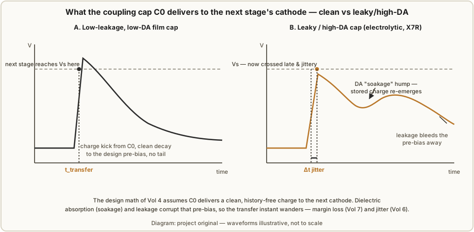
Dielectric absorption (also called soakage or dielectric relaxation) is a capacitor’s tendency to retain a fraction of its charge in the bulk of the dielectric after the plates have been discharged, then release it slowly. The classic demonstration: charge a large cap to some voltage, short it briefly, remove the short — and a residual voltage of a few percent of the original creeps back over seconds. That “returned” voltage, expressed as a percentage of the charging voltage, is the DA figure.
In most circuits DA is a curiosity. In a neon ring it is a timing error, because C0’s
whole job is to deliver a defined charge to the next cathode at a defined moment. If the
dielectric has memory, part of the charge C0 should deliver is instead stuck in the
dielectric and re-emerges later, on its own relaxation time constant, so the pre-bias voltage
on the next stage is neither the clean value the Vol 4 maths assumes nor delivered at the
instant it should be. The stage then reaches Vs at a different time than designed — and,
crucially, at a time that varies pulse-to-pulse and with temperature. That is precisely the
jitter Vol 6 warned about (phase noise on the transfer edges) and a direct erosion of the
margin Vol 7 fights to preserve.
The practical rule follows immediately: use a dielectric whose DA is a small fraction of a
percent, and never an electrolytic (DA of 10–15 %) or a high-K ceramic (X7R, Y5V — a few
percent, and voltage-dependent on top) for C0 or any timing cap.
10.2.2 Leakage — the DC path that shouldn’t exist
Leakage is the small DC current that flows through a real capacitor’s dielectric, modelled
as a very high resistance in parallel with the ideal capacitance. On a 150–250 V rail even a
modest leakage matters twice over. First, it slowly bleeds away the pre-bias charge C0 is
holding on the next cathode, so the head-start the design relies on decays if pulses are
slow or the ring is single-stepped and paused. Second, leakage is strongly
temperature-dependent, so it is itself a drift source. Film dielectrics (polypropylene,
polystyrene, polyester) and Class-1 ceramics (C0G/NP0) have insulation resistances in the
tens-to-hundreds of gigohm-microfarad range — effectively no leakage at these voltages.
Aluminium electrolytics leak microamps-to-milliamps by design; they are wonderful reservoir
caps (Vols 8–9) and completely wrong for coupling.
10.2.3 Value stability — temperature, ageing, and voltage coefficient
The transfer timing and any 555 interval depend on the actual capacitance, so it must not wander. Three effects move it:
- Temperature coefficient. Polystyrene is superb (about −120 ppm/°C, and very repeatable); C0G/NP0 ceramic is specified at 0 ± 30 ppm/°C; polypropylene is a few hundred ppm/°C but smooth and predictable; polyester (Mylar/PET) drifts more and less linearly. High-K ceramics (X7R ±15 %, Y5V +22/−82 % over temperature) are disqualified on this line alone.
- Voltage coefficient of capacitance. Class-2 ceramics (X7R/Y5V) lose capacitance as you apply DC bias — an X7R rated part can shed 20–70 % of its value at rated voltage. On a 150–250 V rail that is catastrophic for a timing element. Film and C0G have essentially no voltage coefficient.
- Ageing. Class-2 ceramics age (lose capacitance logarithmically with time); film and C0G do not, in any way that matters here.
10.2.4 Voltage rating — derate hard
The working-voltage rating must exceed the highest voltage the cap will ever see, with
margin. C0 sits between two cathode nodes but must survive the full swing when the anode
rail collapses and recovers and when a stage strikes, so on a 150–250 V ring a 250 V
part is the sensible floor and 400–630 V is comfortable. Derate film caps to about 50 %
of rating for a long, drift-free life; they are cheap enough that there is no reason not to.
This is why Luc Small chose a 100 nF / 250 V film capacitor for the pulse-coupling cap in
his IN-3 ring on a 150 V rail — a 250 V part on a 150 V rail is a ~1.7× margin, exactly the
right ballpark.
10.2.5 Choosing the dielectric — the comparison
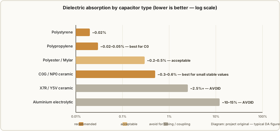
The table and chart below rank the common dielectrics for the coupling/timing role. The
headline: polypropylene is the default best choice for C0 and larger timing caps;
polystyrene is marginally better still on DA and tempco but bulkier and increasingly
hard to source; C0G/NP0 ceramic is the best choice for small, stable values (a few pF
to a few nF — a 555’s timing cap, say); polyester/Mylar is perfectly acceptable if that
is what the drawer holds; and electrolytics and high-K ceramics are to be avoided for any
coupling or timing duty.
Table 1 — 10.2.5 Choosing the dielectric — the comparison
| Dielectric | Dielectric absorption | Tempco | Voltage coeff. | Leakage | Verdict for C0 / timing |
|---|---|---|---|---|---|
| Polystyrene | ~0.01–0.05 % | ~−120 ppm/°C | none | negligible | Excellent; bulky, NOS-ish |
| Polypropylene | ~0.02–0.05 % | ~−200 ppm/°C | none | negligible | Best practical choice for C0 |
| C0G / NP0 ceramic | ~0.3–0.6 % | 0 ± 30 ppm/°C | none | negligible | Best for small stable values (pF–nF) |
| Polyester / Mylar (PET) | ~0.2–0.5 % | ~+400 ppm/°C, nonlinear | slight | very low | Acceptable |
| X7R / Y5V ceramic | ~2.5 %+ | ±15 % / +22−82 % | large (−20…−70 %) | low | Avoid — value collapses under bias |
| Aluminium electrolytic | ~10–15 % | large | — | high (µA–mA) | Avoid (reservoir duty only) |
For a ring built to the Dekker/Luc topology, then, C0 is a polypropylene film cap, 22–100
nF, 250–630 V; a 555 timing cap is C0G ceramic for the small values or polypropylene
for the larger ones; and the only electrolytics in the whole instrument live on the supply’s
reservoir and output filter (Vols 8–9), where their leakage and DA are irrelevant.
10.3 Resistors: voltage coefficient, working voltage, and wattage
The resistors in a ring are unusual in two ways: they are high value (kilohms to hundreds of kilohms) and they sit at high voltage (up to the full supply). Both facts push two resistor specifications — usually ignored at 5 V — to the front: the voltage coefficient of resistance and the maximum working voltage. A third, wattage, is easy but worth a worked example so the derating is honest.
10.3.1 Voltage coefficient of resistance — why carbon composition wrecks the bias
Voltage coefficient of resistance (VCR) is the change in a resistor’s value with the voltage across it, in ppm/V. It arises because in a granular resistive material the conduction paths change slightly with field strength. For the materials we care about:
Table 2 — change slightly with field strength. For the materials we care about
| Resistor type | VCR (typical) | Tolerance | Noise | Notes |
|---|---|---|---|---|
| Metal film | < 0.1 ppm/V (often ~0.01) | 1 % (0.1 % available) | very low | The right choice everywhere in a ring |
| Carbon film | ~−100 ppm/V | 5 % | moderate | Usable for Ra; poor for Rcat |
| Carbon composition | ~−200 to −900 ppm/V | 5–10 % | high | Avoid — value slides under voltage |
Work the numbers to see why this is not academic. The transfer bias I·Rcat is set by
both the lamp current I (fixed by the anode resistor Ra) and Rcat itself, so VCR on
either resistor moves the bias — and the anode resistor is the exposed one, because it drops
the most voltage. In Luc Small’s ring Ra = 120 kΩ drops ≈ 96 V at 800 µA. Take a
carbon-composition Ra with a VCR of −500 ppm/V: across ~96 V its value shifts by
ΔR/R = −500 ppm/V × 96 V ≈ −4.8 % — nearly five times the tolerance you thought you
bought, and in a direction that follows the operating voltage, i.e. it moves as the supply
moves. A −5 % shift in Ra pushes the lamp current up by about 5 %, dragging the transfer
bias I·Rcat up with it by roughly the same fraction — here from 14.4 V to about 15.1 V —
and de-centring the operating current on top. The cathode resistor Rcat drops far less
(only I·Rcat ≈ 14 V), so its own VCR contributes little; but a carbon-composition Rcat
still loses on tolerance, drift and noise (§10.3.4), and any high-value bleeder or feedback
divider sitting across the full rail (§10.3.2) suffers the anode resistor’s problem several
times over. The identical metal-film parts, at < 0.1 ppm/V, shift by under 0.001 % — utterly
negligible, and independent of the supply. This is why the design equations of Vol 4 assume,
and require, metal-film resistors throughout a ring, and why carbon composition — beloved
for its pulse-handling in other contexts — is exactly wrong here.
10.3.2 Maximum working voltage and the series-resistor trick
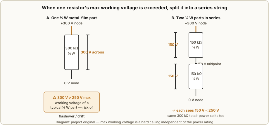
A resistor’s maximum working voltage is a hard ceiling set by physical construction — flashover across the body, arcing between spiral-cut turns in a film part — and it is independent of the power rating. A ¼ W metal-film axial resistor is typically rated 250 V, a ½ W part 350 V, a 1 W part 500 V, regardless of how little power it is actually dissipating. On a neon rail it is entirely possible to be nowhere near the power limit yet well over the voltage limit — a high-value bleeder or feedback divider across a 250–300 V rail, or a dekatron’s anode resistor that momentarily sees the full 400–475 V rail at power-up before any cathode strikes.
The fix is the series-resistor trick: split one resistor into two (or more) in series, so each element sees a fraction of the total voltage while the series sum keeps the design value. Two 150 kΩ ¼ W parts in series make 300 kΩ, each dropping 150 V of a 300 V total — comfortably under the 250 V ceiling — where a single 300 kΩ ¼ W part would be over it. The power splits between them too, which is a bonus, not the point; the point is the voltage. For a dekatron anode resistor on a 450 V rail, two ½ W parts (350 V each) in series clear it easily.
10.3.3 Wattage sizing — two worked examples
Sizing the wattage is the easy part: P = I²R, or equivalently P = V²/R using the voltage
across the part, then derate to about 50 % of the resistor’s rating for longevity and low
drift. Two real rings show how the answer differs.
Luc Small’s IN-3 ring (Inom = 800 µA, Rcat = 18 kΩ, Ra = 120 kΩ, 150 V rail):
Rcat:P = I²R = (0.8 mA)² × 18 kΩ = 11.5 mW, with onlyI·Rcat = 14.4 Vacross it. A ¼ W (250 mW) metal-film part is derated more than 20× — trivially safe on both counts.Ra:P = I²R = (0.8 mA)² × 120 kΩ = 77 mW, withI·Ra = 96 Vacross it — under ¼ W and under 250 V, so a single ¼ W metal-film part suffices with margin.
Dekker’s 10-stage test ring (Ra = 82 kΩ, Rcat = 12 kΩ, up to a 250 V rail, lamp Vm
≈ 100 V):
- Stage current at 250 V — the current runs through
Ra, the lamp, andRcatin series, soI = (Vsupply − Vm)/(Ra + Rcat) = (250 V − 100 V)/(82 kΩ + 12 kΩ) = 1.60 mA. Ra:P = I²R = (1.60 mA)² × 82 kΩ ≈ 210 mW. That is nominally under a ¼ W (250 mW) part, but it sits at 84 % of the rating — far past the 50 % derating target — so Dekker’s higher current and rail pushRato a ½ W part (better a 1 W, to keep the derating near 50 %). The voltage acrossRaisI·Ra = 131 V, well under the ½ W part’s 350 V ceiling.Rcat:P = (1.60 mA)² × 12 kΩ ≈ 31 mWwithI·Rcat≈ 19 V across it — a ¼ W part is fine. (Sanity-check the budget: 131 V acrossRa+ 100 V lamp + 19 V acrossRcat≈ 250 V, the full rail.)
The lesson: the cathode resistors are always featherweight, but the anode resistor’s
wattage tracks the chosen current and rail and can climb until a ¼ W part has no derating
headroom left — always run P = I²R for Ra with your actual numbers, and include Rcat in
the series current calc, rather than assuming.
10.3.4 Tolerance and the bias window
Vol 4 placed the transfer bias I·Rcat at the centre of the hysteresis window, and Vol 3
showed why the tubes themselves must be binned — their Vs/Vm spread is large. The
resistor tolerance stacks on top of that tube spread. With a 12–20 V NE-2 window, a Rcat
that is itself ±5 % (carbon) spends a chunk of your carefully-won margin before the tube
spread is even counted; a ±1 % metal-film Rcat leaves almost the whole window for the tubes.
This is the quantitative reason the parts list calls for 1 % metal film: you are spending
tolerance budget, and the window (Vol 7’s margin) is small, so you buy the tight parts and
keep the budget for the tubes you cannot control. If you are matching a ring to a specific
tube cluster (Luc’s Lower/Middle/Upper bins), 1 % resistors let you actually hit the cluster’s
computed Rcat instead of landing a few percent off and re-measuring.
10.4 How passive choice feeds back into drift (link to Vol 7)
Vol 7 ranked the drift mitigations, and “low-TC, stable passives” earned its place on that
list precisely because of everything above. Restated as a feedback loop: a leaky or high-DA
C0 injects timing jitter and margin loss that looks like tube ageing but is actually the
capacitor; a high-VCR Rcat makes the bias point move with the supply voltage, coupling
supply drift straight into the operating point and undoing the benefit of the stiff regulated
rail you built in Vols 8–9; a high-tempco timing cap makes the step interval breathe with room
temperature. Choose film and C0G caps and 1 % metal-film resistors and you have removed the
passives from the list of suspects entirely — so that when the ring does eventually drift,
you know it is the tubes (Vol 7’s honest conclusion from the PA3FWM clock), and you can
address it with binning, burn-in, and priming rather than chasing a capacitor you should
never have used.
10.5 Recommended passives — a shopping table
The table below is the “just tell me what to buy” summary for a Dekker/Luc-style neon ring on
a 150–250 V rail. Values are per the reference build of Vol 13; substitute your cluster’s
computed Rcat/Ra from Vol 4.
Table 3 — 10.5 Recommended passives — a shopping table
| Role | Buy | Value (example) | Rating | Why |
|---|---|---|---|---|
Coupling cap C0 | Polypropylene film | 22–100 nF | 250–630 V | Low DA + leakage; clean transfer |
| 555 timing cap (small) | C0G / NP0 ceramic | pF–nF | ≥ 50 V | Zero tempco/voltage coeff, stable interval |
| 555 timing cap (large) | Polypropylene film | 0.1–10 µF | ≥ 50 V | Stable run frequency, low leakage |
Cathode resistor Rcat | Metal film, 1 % | ~12–18 kΩ | ¼ W | Low VCR + tight tolerance centres the bias |
Anode resistor Ra | Metal film, 1 % | ~82–120 kΩ | ½–1 W, ≥ 350 V | Carries stage current; run P = I²R |
| HV bleeder / feedback | Metal film, series string | per design | derate to 50 % | Split so each part stays under its max working voltage |
| Supply reservoir/filter | Aluminium electrolytic | per Vols 8–9 | ≥ 1.5× rail | DA/leakage irrelevant here — bulk energy only |

10.6 10.x References
- R. Dekker (dos4ever), “A Neon Ring Counter” / Ring Counter Variations — https://www.dos4ever.com/ring/ring.html — the design equations and the 82 kΩ / 12 kΩ / 27 nF test-ring values used in the worked examples.
- L. Small, “Neon Ring Counters” (2016) — https://lucsmall.com/2016/10/08/neon-ring-counters/ — the 150 V / 800 µA / 18 kΩ / 120 kΩ IN-3 ring and its 100 nF / 250 V film coupling capacitor.
- J. B. Dance, Electronic Counting Circuits (Iliffe / American Elsevier, 1967) — in the site’s reference library — classic cold-cathode component practice.
- Wikipedia, “Dielectric absorption” — https://en.wikipedia.org/wiki/Dielectric_absorption — DA figures for film, ceramic, and electrolytic dielectrics.
- Analog Devices, “Ask the Applications Engineer — 24: Resistance” — https://www.analog.com/en/resources/analog-dialogue/articles/ask-the-applications-engineer-24.html — resistor voltage coefficient and self-heating.
- Cross-references: Vol 2 (relaxation-oscillator period), Vol 3 (tube binning), Vol 4 (ring design equations,
C0/Rcat/Ra), Vol 6 (jitter), Vol 7 (drift & margins), Vols 8–9 (HV supplies, reservoir caps), Vol 13 (reference build BOM), Vol 14 (safety).
Comments (0)