Neon Ring Counters · Volume 1
Overview & the Cold-Cathode Counting Idea
What a neon ring counter is, why a glowing dot can count, and how to read this series
A neon ring counter counts by moving a single dot of orange light around a circle of little glow lamps — one lamp brightens for each pulse you feed in, the glow steps to the next lamp, and when it reaches the end of the ring it hands a pulse to the next ring and starts over. There are no transistors in the count path, no logic gates in the usual sense, and depending on how purist you are, arguably no “components” doing the thinking at all: the memory, the switching, and the display are all the same physical thing — a bit of neon gas that is either glowing or dark. It is the most literal digital display ever built, because the “1” is not a numeral drawn on a screen but an actual lit lamp, and it is one of the few places in electronics where you can watch a circuit count with your own eyes at a human pace. That a cheap indicator lamp — the same NE-2 that has been the “power on” pilot light in ten thousand appliances — can be coaxed into remembering a state and passing it to its neighbour is one of the small miracles of gas-discharge physics, and this series is about exploiting it.
This fifteen-volume reference covers the neon lamp as a switching device rather than a mere indicator: the glow-discharge physics that gives it memory (Vol 2), which lamps and tubes actually work and how to sort the good ones from the bad (Vol 3), the ring counter’s theory of operation and its design mathematics (Vol 4), the dekatron — a whole ten-stage ring packed into a single glass envelope (Vol 5), how accurately these things divide a frequency and why that question has a subtle answer (Vol 6), the drift and ageing that will otherwise defeat you and how to fight it (Vol 7), the high-voltage supplies that feed the whole thing in both their traditional valve-and-VR-tube form and their modern boost-converter form, with schematics (Vols 8–9), which capacitors and resistors to actually buy (Vol 10), a buildable burn-in jig for conditioning and sorting tubes (Vol 11), a heavily illustrated gallery of real applications from computers to organs (Vol 12), a complete buildable reference ring counter (Vol 13), the safety discipline the ~100–450 V rails demand (Vol 14), and a laminate-ready cheatsheet (Vol 15). It is written for an experienced maker with a bench, a high-voltage-capable meter, and the patience to characterise a box of surplus lamps before trusting any of them.
1.1 Why a glow lamp can count
Everything in this series rests on one property of a gas discharge: it does not turn on and
off at the same voltage. A neon lamp stays dark until the voltage across it climbs to its
striking voltage Vs — the point where the gas breaks down and ionises — and once lit,
it will keep glowing until the voltage falls all the way back down to a much lower
maintaining voltage Vm, at which the discharge can no longer sustain itself. Between
Vm and Vs the lamp is bistable: which state it is in depends on its recent history,
not just on the present voltage. That gap between striking and maintaining — the
hysteresis — is memory. A device with memory that also emits light and switches a real
current is already 90 % of a display-counter; all that remains is to wire a chain of them so
that extinguishing one lamp preferentially lights the next one, and always in the same
direction.
That is exactly what a ring counter does, and Vol 4 works through the mechanism pulse by pulse. For now the picture to hold in your head is a circle of neon lamps sharing one high-voltage rail, each with a small resistor in its cathode leg and a small capacitor linking it to its neighbour. Exactly one lamp is lit at any moment. A pulse momentarily collapses the shared rail, the lit lamp goes out, and the coupling capacitor — charged by the lamp that was just on — gives the next lamp around the ring a head start so that when the rail recovers, it strikes first. The dot has moved one place. Feed the ring ten pulses and the dot has gone once around; tap the tenth lamp and you have divided the input by ten.
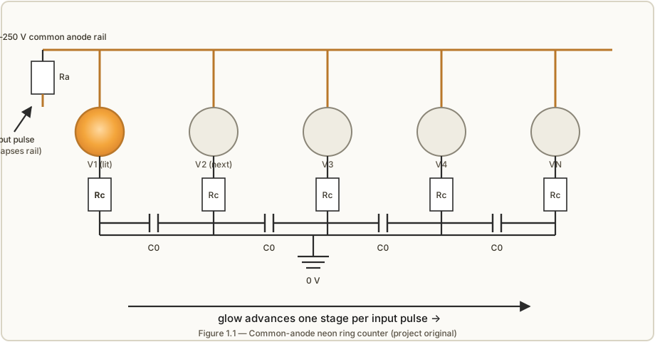
1.2 The four things a neon counter is made of
Strip a neon-counting instrument down and it is always the same four subsystems, whatever era it comes from:
- The lamps or tubes — cold-cathode neon devices used as switches, not just pilots. These range from the humble NE-2 indicator (cheap, plentiful, and electrically marginal), through Soviet surplus IN-3s, up to purpose-built switching tubes like the Philips ZA1002 with a wide, robust hysteresis window, and finally the dekatron, which is a complete ring in one envelope (Vols 3, 5).
- A high-voltage supply — the lamps will not strike until the rail sits comfortably above
Vs, which for a chain of switching tubes can mean 150–250 V and for dekatrons 400 V or more. That rail must be stable, because every volt of supply drift eats directly into the design margins. The old way is a valve rectifier and a VR-tube shunt regulator; the new way is a small boost converter (Vols 8, 9). This is the part that can hurt you. - The coupling and steering network — the resistors and capacitors that turn a row of independent lamps into a directional shift register. This is where the design maths lives, and where the difference between “works on the bench for an afternoon” and “runs for a year” is decided (Vols 4, 10).
- A pulse source and readout — something to feed the ring (a mains-derived tick, a 555, an oscillator to be divided) and some way to get the count back out (read the lit lamp by eye, or tap a cathode for a carry pulse, or — as in the neon clock of Vol 12 — sense the glow with a light-dependent resistor).
Three of those four are easy. The lamps are bought, the pulse source is trivial, the readout is often just your eyes. The high voltage and the steering network sit right where “fascinating” meets “will bite you,” and that is where this series spends its pages.
1.3 A one-paragraph history
The counting properties of glow discharge were understood well before the transistor. The
canonical ring counter appears in Manley and Buckley’s 1950 Electronics article, which
steered the glow with germanium diodes; through the 1950s and 60s cold-cathode counting became
a mature industrial art, its bible being J. B. Dance’s Electronic Counting Circuits (1967)
— the book, held in this project’s shared reference library, that every modern experimenter in
this field still cites. The star of the era was the dekatron, the glow-transfer decade
counter that put a spinning dot of light behind a numbered dial; dekatrons scaled pulses in
physics labs, drove the ANITA desktop calculator, and stored numbers in the WITCH
(Harwell Dekatron) computer, which still runs at The National Museum of Computing (Vol 5, Vol
12). Purpose-built switching and trigger tubes — the Philips ZA1001/ZA1002 family among
them — extended the idea into fast, reliable logic, and in one gloriously stubborn commercial
product, the early all-tube Philips Philicorda organ, banks of neon tubes divided a
top-octave oscillator down into the lower octaves, giving the instrument its warm, faintly
unstable voice (Vol 6, and the sibling Philicorda/ dive). Silicon killed all of this for the
usual reasons — cheaper, lower-voltage, solid-state — but it never made it un-beautiful, and a
steady undercurrent of hobbyists (Ronald Dekker’s and Luc Small’s modern ring counters, Pieter-
Tjerk de Boer’s silicon-free neon clock) keeps the craft alive. This series stands squarely on
their work.
1.4 What you can build, and where each is covered
There is no single “the” neon counter — there is a spectrum, from a two-lamp novelty flasher to a full clock that keeps time in glowing gas. This dive recognises five first-class paths and points each at its home volume.
Table 1 — 1.4 What you can build, and where each is covered
| # | Path | Effort | Where |
|---|---|---|---|
| 1 | A neon relaxation oscillator / flasher — one lamp, one R, one C; the “hello world” | trivial | Vols 2, 12 |
| 2 | A ring counter from indicator neons (NE-2 / IN-3), binned and burned-in | medium | Vols 4, 11, 13 |
| 3 | A ring counter from switching tubes (ZA1002) — robust, wide-margin, NOS-dependent | medium | Vols 3, 4, 13 |
| 4 | A dekatron scaler/counter — one tube per decade, a numbered dial | medium | Vols 5, 8 |
| 5 | A full neon-logic clock or divider chain — the PA3FWM clock, organ-style dividers | very high | Vols 6, 7, 12 |
Path 2 is the worked example that runs through the engineering volumes: Vol 13 builds a complete reference ring counter that synthesises Ronald Dekker’s design equations with Luc Small’s measured component values for real surplus IN-3 lamps, driven by a 555-based step/run pulser on a 150 V rail. Path 5 is the aspirational showpiece — a clock whose every counting element is a glow — and Vol 12 dissects the best real example of it.
1.5 Decision tree — where to start
Work top-down; stop at the first “yes.”
- Do you just want to see the effect work tonight, with parts already in a drawer? → Build a
neon relaxation oscillator (Vol 2’s
Vs/Vmsection shows the maths; Vol 12 shows variants). It is the fastest possible confidence-builder and teaches the hysteresis you will lean on everywhere else. - Do you have a bag of cheap surplus neons and want them to count? → You are on Path 2. Read Vol 3 on why those lamps are electrically marginal, build the burn-in jig of Vol 11 to condition and bin them, then build the reference ring of Vol 13. Do not skip the binning — it is the single biggest predictor of whether your ring works.
- Do you have (or can you buy) real switching tubes and want reliability over authenticity of
the cheap-lamp challenge? → Path 3. The wide
Vs−Vmwindow of a ZA1002 (Vol 3) makes the ring far more forgiving; mind the decayed-tritium striking problem for very old stock. - Do you want a numbered decade display, not a raw ring? → Path 4, a dekatron (Vol 5). One tube replaces ten lamps and the steering network, at the cost of a higher supply voltage and scarcer, pricier tubes.
- Do you want the full trophy — a working clock or a musical octave divider built from glow? → Path 5. Read Vols 6 and 7 first: frequency division has a subtle accuracy story, and drift is what will actually decide whether your clock survives a year (the honest answer, from PA3FWM, is that it may not — and Vol 7 is about pushing that horizon out as far as it will go).
1.6 A word on high voltage, up front
Every path above except the single-lamp flasher runs on a rail between roughly 100 V and 450 V DC, sitting behind a reservoir capacitor that stays charged after you switch off. That is more than enough to hurt or kill you, and unlike mains it does not trip anything or announce itself. ⚠ Treat every rail in this series as lethal until you have proven it discharged with a meter. Vol 14 is the full safety discipline — the single-hand rule, the bleeder resistor, the discharge tool, insulated probing — and it is not optional reading. The tubes are beautiful and the effect is gentle to watch; the electricity behind it is not gentle at all.
1.7 How to read this series
Vols 2–7 are the understanding half — physics, tubes, ring theory, dekatrons, division accuracy, and drift — and reward reading in order, because each leans on the last. Vols 8–11 are the supporting engineering — supplies, passives, and the burn-in jig — and can be dipped into as a build demands. Vol 12 is the illustrated payoff, a gallery of everything the technique has ever been used for. Vol 13 is the hands-on build. Vols 14–15 are the safety discipline and the quick-reference card you will actually keep on the bench. Throughout, the canonical citation is Dance’s Electronic Counting Circuits; the modern practical companions are Dekker’s ring-counter pages and Luc Small’s build log; and the running cautionary tale is de Boer’s neon clock, which did everything right and still teaches the hardest lesson in the field — that a neon lamp is never quite finished changing.
References
- J. B. Dance, Electronic Counting Circuits (London: Iliffe Books / New York: American Elsevier, 1967) — in the site’s reference library.
- R. Dekker, “A Neon Ring Counter” / Ring Counter Variations — https://www.dos4ever.com/ring/ring.html
- L. Small, “Neon Ring Counters” (2016) — https://lucsmall.com/2016/10/08/neon-ring-counters/
- P.-T. de Boer (PA3FWM), “A clock using neon lamps as logic elements” — https://www.pa3fwm.nl/projects/neonclock/
- Manley & Buckley, “Neon Ring Counter,” Electronics, January 1950.
Comments (0)