CubeSat Simulator · Volume 3
The Build — Vol 3
The Build — Vol 3
Introduction
This volume is the build: what parts go into a CubeSatSim, how the three custom boards are populated and stacked, how the power subsystem goes together, and how the software is loaded. It is written against the v2.1 hardware — the current revision in the GitHub hardware/ tree — whose schematics and bills of materials are the primary source for everything below.1 Component-level detail is extracted directly from the v2.1 BOM CSVs and schematics; the full circuit walk lives in 02-inputs/research/build-and-schematic-notes.md, and Vol 4 annotates the schematics themselves.
Two ways to get one. You can buy the kit (AMSAT sells assembled boards + parts) or build from the open-source files (order the PCBs from the gerbers, buy the BOM parts, hand-populate). The kit ships the three boards assembled, a programmed Pi Zero 2, the Pico, sensors, battery hardware, and the 10 solar panels.2 This volume covers the from-files path and explains the kit’s pieces along the way.
1. The big picture — what’s in a CubeSatSim
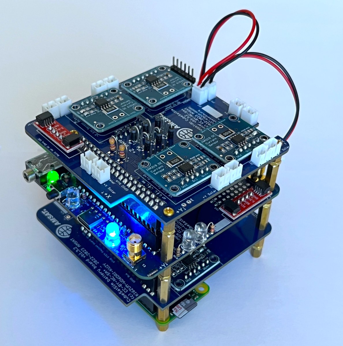
The whole simulator, module by module:
Table 1 — The whole simulator, module by module
| Module | Part | Role |
|---|---|---|
| Flight computer | Raspberry Pi Zero 2 (WH) + programmed micro-SD | runs the CubeSatSim software, telemetry, SSTV, modes |
| Payload MCU | Raspberry Pi Pico (RP2040) on the Main board | STEM-payload brain; can run standalone without the Pi |
| Main board (STEM Payload Board) | custom PCB | radio + audio + sensors + power/charge control + user I/O |
| Battery board | custom PCB | holds 3× AA NiMH; battery V/I telemetry |
| Solar board | custom PCB | combines 10 solar panels; per-panel current telemetry |
| Power | 3× AA NiMH cells, 10× solar panels (~5.5 V), USB-C input | self-powered sun/eclipse operation |
| Sensors | MPU6050 (IMU+temp), BME280 (temp/pressure/humidity), diode temp | the “science” telemetry |
| RF | SR105U SR_FRS 0.5 W UHF FM module (legacy alt: DRA818/SA818), 2× SMA antennas | the 70 cm downlink |
| Structure | 3D-printed 1U frame | holds the stack, battery, panels, antenna |
The boards interconnect two ways: the Main board’s 20×2 (40-pin) stacking header mates to the Pi Zero’s GPIO, and the Battery and Solar boards link by Micro-JST jumpers.1
2. Bill of materials — reading the BOM
The authoritative parts lists are the per-board CSVs (cubesatsim-{main,battery,solar}-v2.1.0_bom.csv.txt) and the CubeSatSim Main v2.1.0 BOM.xls, all in the GitHub hardware/v2.1 folder; a human-readable copy lives at cubesatsim.org/bom.13
Watch the
DNIprefix. The BOMs list every footprint on the board, but a large fraction are markedDNI/…(“Do Not Install”) — they are alternate/optional positions (SMD vs through-hole variants, optional RF parts, address-select jumpers). The populated set is a subset. Don’t order the DNI parts unless you’re choosing that alternative. For example, the Main board lists both through-hole and 0603 SMD versions of many resistors with one of each pair marked DNI.
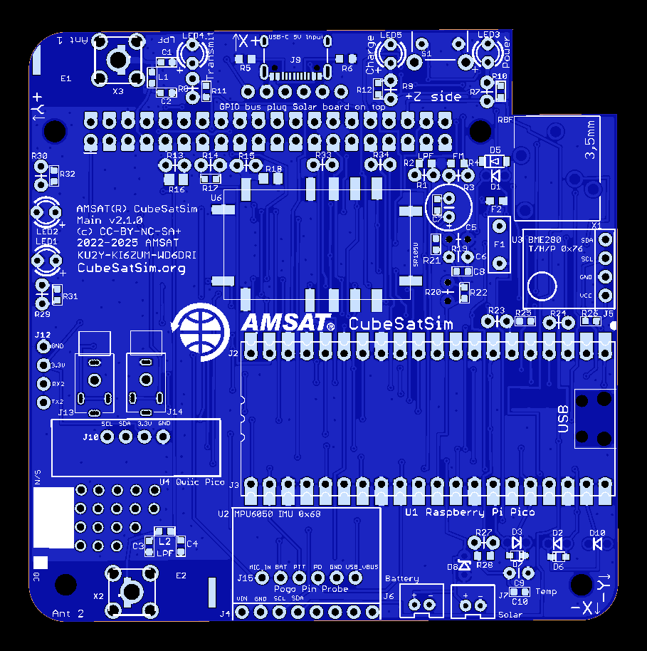
Main board — key populated parts
Table 2 — Main board — key populated parts
| Ref | Part | Function |
|---|---|---|
| U1 | Raspberry Pi Pico | payload microcontroller |
| U6 | SR105U SR_FRS 0.5 W UHF FM module (U7 = DRA818/SA818 legacy alt, “check availability”) | the transmitter |
| L1,L2 / C1–C4 | 13 nH / 16–18 pF | UHF low-pass filter (×2, one per antenna) |
| X2, X3 | SMA-VERT | Antenna 1 / Antenna 2 |
| U2(J4) / U3(J5) | MPU6050 / BME280 | IMU+temp / temp-pressure-humidity |
| D3 | 1N4148 | diode temperature sensor |
| LED1–5 | White/Yellow/Green/Blue/Red 5 mm | status + mode indication |
| S1 | RA-SPST | mode push-button |
| J8 | SparkFun USB-C breakout | power/charge input |
| F1 | RHEF100-2 PTC | battery-path resettable fuse |
| D1 | BYW27-400 | power steering diode |
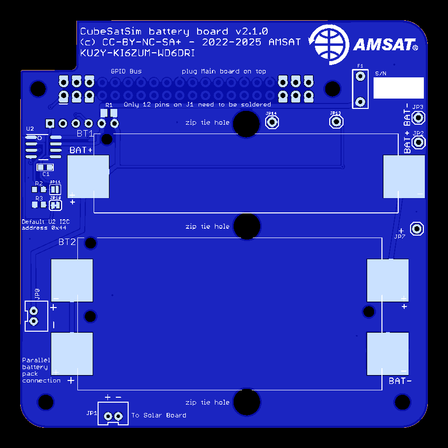
Battery board
3× AA NiMH in BT1/BT2 holders; INA219AIDR (U2) high-side V/I monitor with a 0.1 Ω shunt; 10 kΩ I²C pull-ups; PTC fuse. I²C address 0x44 (primary), 0x45 (secondary, bridge JP11).1
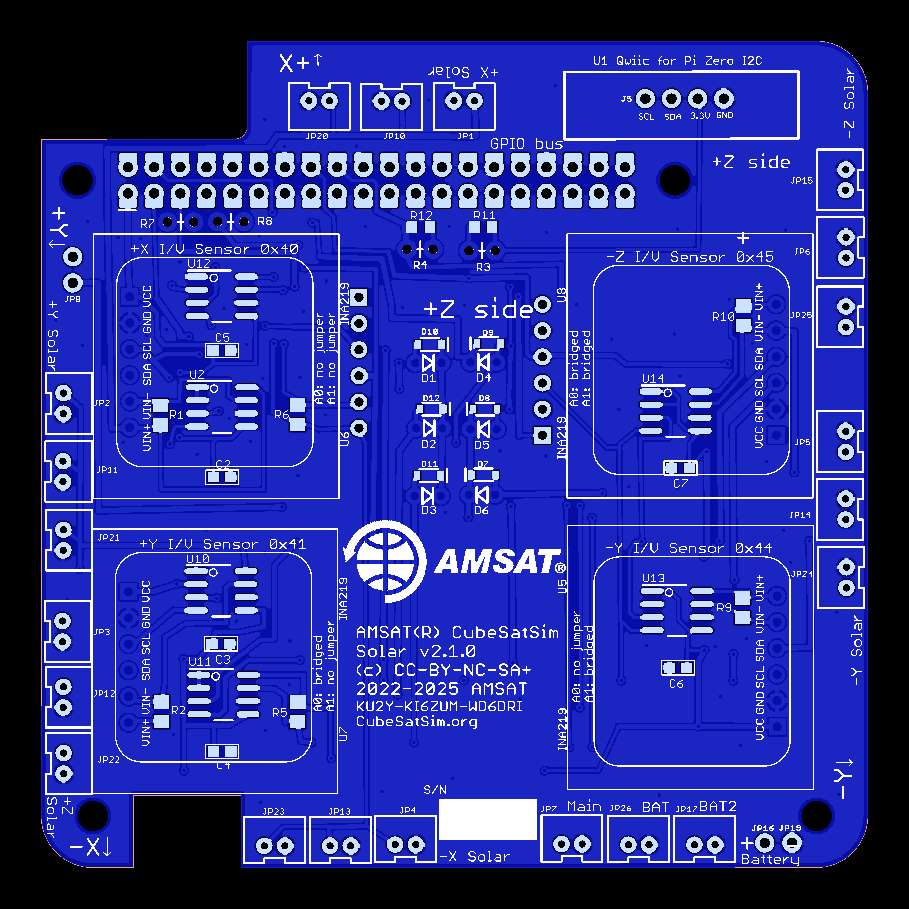
Solar board
~12× INA219 current monitors (one per panel input) each with a 0.1 Ω shunt; Schottky blocking diodes (1N5817 + BAT20J) to OR the panels; a bank of Micro-JST connectors for the panel leads; 4.7 kΩ I²C pull-ups.1
3. Fabricating the PCBs
If building from files: each board folder ships *_gerbers.zip (fab files + drill), *_centroid.zip (pick-and-place), and .mnt/.mnb SMD placement data. The project fabricates at PCBWay, but any fab that accepts gerbers works.1 Order all three boards. Most parts are hand-solderable (through-hole headers, 5 mm LEDs, AA holders, SMA jacks); the SMD positions are 0603/SOD and the modules (Pico, INA219 “purple boards”, FM module) mount on headers/sockets, which keeps a hand build realistic.
4. Assembly & configuration jumpers
The Main board is highly configurable via solder jumpers — the build is as much jumper selection as soldering.1 The key solder-jumper choices (from the v2.1 schematic notes):
Table 3 — The Main board is highly configurable via solder jumpers — the build is as much jumper selection as soldering.[^hw] The key solder-jumper choices (from the v2.1 schematic notes)
| Jumper | Default / action | Why |
|---|---|---|
| JP2 | bridge to bypass the 17 dB attenuator | attenuator drops ~500 mW → ~10 mW for safe low-power TX |
| JP11 | cut to let the FM module transmit high power (~500 mW) | (always bridge JP2 too) |
| RBF / JP4 | install the Remove-Before-Flight switch; bridge if not used | the “launch” interlock — pulling it powers up |
| JP10 | bridge if PTC fuse F1/F2 not used | the PTC replaces an earlier diode (D4) |
| JP1 | bridge to let the Pico power & charge the battery | charging is Pico-managed from the USB-C 5 V rail |
| JP6 / JP8 | cut JP6 + bridge JP8 to let the Pico program the FM module | initial module config |
| Antenna 1/2 jumpers | bridge for single-antenna use; cut for dual | selects one or both SMA outputs |
| R1/R2, R3/R4 | a 1 kΩ in R1/R2 ⇒ UHF LPF present; in R3/R4 ⇒ SR105U fitted | board self-identifies its variant to firmware |
Power-subsystem build order that matters: the RBF switch gates power — with it pulled, the board is live. Always assemble and test with the RBF in (system off), and use the USB-C input for bench power/charging before relying on battery + solar.
5. Loading the software
Two processors get programmed:
- Raspberry Pi Zero 2 — flash the CubeSatSim micro-SD image (kits ship it pre-programmed). On first setup you run the software install, which prompts for your amateur callsign — this is what the transmitter sends as its CW ID, so it is a licensing requirement, not a cosmetic step.4
- Raspberry Pi Pico — flashed with the CubeSatSim Pico firmware (the kit’s Pico is “fully programmed”).2 The board jumpers above let the Pico self-program the FM module on first boot.
The step-by-step flashing, OS image URL, and
configoptions are maintained on the project wiki and are best transcribed there at build time (the wiki is the living source; this deep dive cites it rather than freezing a version that will drift). The boot/run sequence and ground-station decode are covered in Vol 5.
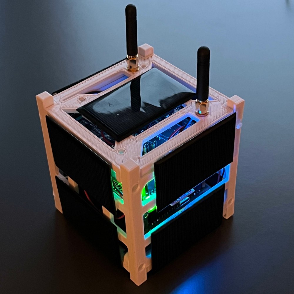
6. Mechanical — the 1U frame
The electronics drop into a 3D-printed 1U frame (print files in the GitHub hardware/frame folder).1 The frame holds the board stack, the battery holders, the 10 solar panels on the cube faces, and the SMA antenna(s). Printing and final mechanical integration is the last build step before the power-up sequence in Vol 5.
7. Machining the 1U frame from aluminum (Carbide 3D Nomad 3)
The printed frame in §6 is the quick path. The other path — the one I take — is to cut the frame from 6061 aluminum on a desktop CNC, a Carbide 3D Nomad 3.5 An aluminum frame is stiffer, carries real machine threads that survive being assembled and disassembled dozens of times, gives the board stack a solid ground/EMI reference and some thermal mass, and simply looks the part. The trade is time, tooling, and a machine; PLA is lighter, cheaper, and perfectly adequate for a windowsill demo. This section is the recipe for doing it on a Nomad-class machine — including the part everyone asks about, tapping, which on a machine with no rigid-tapping spindle has two distinct answers.
Two scopes — pick before you cut.
- Full aluminum — the four corner rails and the two interior board-mount plates (and, if you want, closed face panels) are all machined from 6061.
- Hybrid — machine only the four load-bearing corner rails in aluminum and keep the 3D-printed interior board plates from §6. This is the high-value/low-effort version: you get the rigid, threadable structure where it matters and skip the fiddliest parts.
7.1 Reference geometry — what you’re actually cutting
Drive the CAM from the CubeSat Design Specification (CDS) 1U envelope: 100.0 mm × 100.0 mm × 113.5 mm external, with the structural rails running the 113.5 mm axis on the four corners (rail face ≥ 8.5 mm wide).6 The CubeSatSim’s own frame is a simplified educational 1U — it sits in the same geometry but is not built to deployer-rail tolerances, so you don’t need flight-grade rail finishes. In practice: take the outside envelope and rail layout from the CDS, and take the board-mount hole pattern, standoff heights, and panel cut-outs directly from the upstream print files (the STLs in the GitHub hardware/frame folder — measure them, since they’re meshes meant for a printer, not parametric CAD).1 Fastening is M3 throughout the structure; the Pi/board standoffs are commonly M2.5 — confirm against the parts you have before you drill.
The machined part count is small: 4 corner rails, 2 board-mount plates, and (optionally) face panels — though the faces usually stay open frames so the 10 solar panels and antennas mount cleanly.
7.2 The Nomad’s envelope is the real constraint
The Nomad 3 work envelope is 203 mm × 203 mm × 76 mm (8″ × 8″ × 3″).5 Notice the Z: 76 mm of travel, but a 1U rail is 113.5 mm long. You therefore cannot stand a rail upright and machine it end-on — it won’t fit under the spindle. The fix is simple and it dictates your whole workholding plan:
- Rails lie flat. Machine each rail with its long (113.5 mm) axis in X or Y (where you have 203 mm), cutting the cross-section profile, the board-mount holes, and the tapped holes from the top, then flip the part to do features on the opposite face.
- Plates lie flat — they’re well within the envelope and are the easy parts.
7.3 Stock & material
Use 6061-T6: it machines cleanly, anodizes well, and is plenty strong for a 1U. Buy stock close to the finished section and sized to the bed, so you remove little metal.
Aluminum stock by part:
Table 4 — Aluminum stock by part
| Part | Stock | Notes |
|---|---|---|
| Corner rails | 12 mm (or ½″) square bar, cut to ~120 mm | square bar for full rails; angle extrusion is a fast shortcut for the hybrid scope |
| Board-mount plates | 3–6 mm plate | 3 mm is ample; 6 mm if you want tapped edges |
| Face panels (optional) | 2–3 mm sheet | usually left open for solar panels |
7075 buys more strength if you ever want it, but it costs more and won’t anodize clear — unnecessary here.
7.4 CAM & cutting on the Nomad
Any of MeshCAM (bundled with the Nomad), Fusion 360, or Carbide Create Pro will drive it. The flow is the usual desktop-CNC loop: set stock, zero the job (a probe/BitZero or a paper-feeler touch-off), clamp the work, then run roughing → finishing → drilling → threading toolpaths, flipping the part between setups where §7.2 requires it.
- Workholding: the Nomad’s threaded bed / fixture plate with low-profile clamps for bar stock; painter’s-tape-and-CA-glue for thin plates; leave tabs on profile cuts so parts don’t break loose on the last pass.
- Tooling: a spot drill; a 2.5 mm stub drill (the M3 tap-drill); a 1/8″ (3.175 mm) 3-flute carbide endmill for adaptive clearing (single-flute also works well in aluminum); a smaller endmill for detail; a chamfer mill; and — for Route B below — an M3 single-form thread mill.
Feeds and speeds are conservative 6061 starting points — confirm by chip color and sound, and cross-check Carbide 3D’s published 6061 presets.
Starting feeds and speeds for 6061:
Table 5 — Starting feeds and speeds for 6061
| Operation | Tool | Spindle | Feed | Depth |
|---|---|---|---|---|
| Adaptive clearing | 1/8″ 3-flute carbide | 16,000 rpm | ~900 mm/min (≈35 in/min) | 0.4 mm radial (WOC), 3 mm axial (DOC) |
| Finish profile | 1/8″ 3-flute carbide | 16,000 rpm | ~700 mm/min (≈27 in/min) | 0.1 mm radial, full depth in passes |
| Drill (2.5 mm) | stub drill | 6,000 rpm | 120 mm/min, peck 0.5 mm | to depth |
| Thread mill (M3) | M3 single-form | 12,000 rpm | per CAM helical | 1–2 radial passes + spring pass |
No flood coolant — plan for it. The Nomad is enclosed but doesn’t flood. Aluminum welds to a dry, slow cutter (built-up edge), which then snowballs into a broken tool. Run an air blast or mist and a lubricant (WD-40, IPA, or an aluminum cutting fluid), use climb milling with adaptive/trochoidal paths to keep chips thin and moving, and don’t let the tool rub at low feed.
7.5 Threads — the two routes (this is the “tapping, etc.”)
The board standoffs, rail joints, and panel mounts are M3×0.5. Both routes start identically on the CNC — spot-drill, then drill the hole pattern — and only diverge at the thread itself.

Route A — CNC-drill, then hand-tap. Drill the 2.5 mm tap-drill on the machine, chamfer the hole mouth (~0.3 mm), then hand-tap off-machine. Keep the tap square with a tapping block — or chuck the tap in the de-powered spindle and turn it by hand so the spindle bearings hold it true. Use a spiral-point (“gun”) tap for through-holes, plenty of cutting fluid, and peck (a quarter-turn back every half-turn) to break and clear chips. Cheap, fast for a few holes — but a tap can snap in a blind hole, and once it does it’s a bad afternoon.
Route B — thread-mill on the Nomad. Drill to the minor diameter (~2.5 mm), then helically interpolate the M3 thread form with a single-form thread mill (climb, one or two radial passes plus a spring pass). The Nomad has no rigid tapping — no spindle encoder to synchronize feed to a tap — so this is the machine-native way to make threads: it needs no synchronized spindle, it’s repeatable across many holes, and if a pass goes wrong you don’t have a broken tap stuck in the part — you just re-run it. The cost is CAM setup and a small, delicate tool that you must treat gently.
Hand-tap versus thread-mill:
Table 6 — Hand-tap versus thread-mill
| Route A — hand-tap | Route B — thread-mill | |
|---|---|---|
| Tooling cost | low (one tap) | higher (thread mill + CAM) |
| Setup | minimal | CAM toolpath per hole |
| Repeatability | operator-dependent | excellent |
| Failure mode | broken tap in the hole | re-run the pass |
| Blind holes | risky | clean |
| Best for | a few through-holes, one-offs | blind holes, many holes, repeat parts |
A third option for durability/repair: thread inserts — a Helicoil/Time-Sert in a tapped-and-installed hole gives steel threads in the aluminum, ideal for a joint you’ll cycle often or to rescue a hole you’ve stripped. (The plastic-only heat-set inserts from the printed-frame world don’t belong in aluminum.)
7.6 Deburr, finish, assemble
Deburr every edge and tapped hole. Optional bead-blast + anodize gives a hard, handsome, corrosion-resistant surface (and lets you color-code parts). Assemble with stainless M3 hardware and a dab of thread-locker — and because stainless screws gall in aluminum threads, use anti-seize and don’t over-torque (M3 in aluminum wants roughly 0.5–1 N·m, snug, not gorilla-tight). The RBF interlock, panel, and antenna mounting from §6 all carry over unchanged.
7.7 Printed vs machined — at a glance
Printed versus machined, at a glance:
Table 7 — Printed versus machined, at a glance
| 3D-printed (§6) | Machined 6061 (§7) | |
|---|---|---|
| Tooling needed | a printer | a CNC (Nomad 3) + endmills/taps |
| Build time | hours, mostly unattended | a day of setups + flips |
| Cost | filament | 6061 stock + tooling |
| Mass | lightest | heavier (more thermal mass) |
| Rigidity | adequate | high |
| Threads | heat-set inserts / self-tap | real M3 (tapped or thread-milled) |
| Best for | quick demo, classroom sets | a durable, flight-like personal build |
References
Footnotes
-
CubeSatSim hardware v2.1 — schematics + BOM CSVs + gerbers — https://github.com/alanbjohnston/CubeSatSim/tree/master/hardware/v2.1 (and the local copies in
02-inputs/research/schematics/). Board files © CC-BY-NC-SA AMSAT. ↩ ↩2 ↩3 ↩4 ↩5 ↩6 ↩7 ↩8 ↩9 -
CubeSatSim Wiki — Kit — https://github.com/alanbjohnston/CubeSatSim/wiki/Kit (assembled boards, programmed Pi Zero 2, Pico W, 10× solar panels). ↩ ↩2
-
CubeSatSim BOM — https://cubesatsim.org/bom. ↩
-
“AMSAT CubeSatSim” (Paper 7) — https://cubesatsim.com/content/CubeSatSimPaper7.pdf (callsign entered during install; CW “de
” ID). ↩ -
Carbide 3D Nomad 3 desktop CNC — work envelope 203 × 203 × 76 mm (8″ × 8″ × 3″), ER-11 collet spindle to ~24,000 rpm, no rigid/synchronized tapping — https://carbide3d.com/nomad/. Bundled CAM is MeshCAM. Feeds/speeds here are conservative 6061 starting points; cross-check Carbide 3D’s published 6061 presets and tune by chip/sound. ↩ ↩2
-
CubeSat Design Specification (CDS), Cal Poly — 1U external envelope 100.0 × 100.0 × 113.5 mm, corner rails on the 113.5 mm axis — https://www.cubesat.org/cubesatinfo. The CubeSatSim frame is a simplified educational 1U (not built to deployer-rail tolerances). ↩