CubeSat Simulator · Volume 1
The System — Vol 1
The System — Vol 1
Introduction
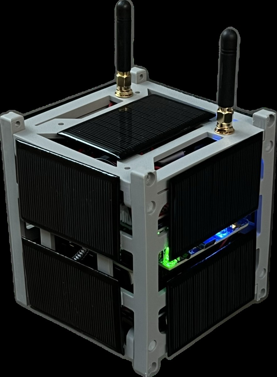
The AMSAT CubeSatSim is a fully open-source, low-cost satellite emulator — a working, ground-based functional model of a “1U” CubeSat nanosatellite. It is built around a Raspberry Pi, housed in a 3D-printed frame, powered by onboard rechargeable batteries and solar panels, and it transmits authentic voltage, current, and temperature telemetry over the amateur-radio UHF (70 cm) band, exactly the way a real CubeSat in Low Earth Orbit (LEO) does.123 Created by Alan Johnston (KU2Y) and developed under the umbrella of AMSAT (the Radio Amateur Satellite Corporation), it exists so that students, educators, and radio amateurs can learn satellite engineering and practice satellite ground-station operation on the bench, without needing a satellite in orbit.
This volume is the map for the rest of the deep dive: what the thing is, what subsystems it is made of, and how those subsystems fit together. Later volumes go deep on the theory (Vol 2), the build and bill of materials (Vol 3), the schematics (Vol 4), and ground-station usage (Vol 5).
What the CubeSatSim is — and isn’t
A real CubeSat is a small satellite built up from 10 cm cubic units (“U”): a 1U CubeSat is a single 10 × 10 × 10 cm cube. The CubeSatSim is a functional model of a 1U CubeSat: it is the same size and shape, and it reproduces the behaviors that matter for learning — solar/battery power management, sensor telemetry, and a real RF downlink — while running safely on the ground.21
What it reproduces faithfully:
- Self-powered operation from rechargeable batteries charged by solar panels, just like a LEO satellite cycling through sunlight and eclipse.13
- A real radio downlink in the 70 cm amateur band, carrying genuine housekeeping telemetry (bus voltages, currents, temperatures) plus camera imagery.45
- The ground-station experience — you point an antenna, tune an SDR, and decode the telemetry with the same tools used for flight satellites (AMSAT FoxTelem).1
What it is not: it does not go to orbit, and (in normal use) it transmits at low power into a local antenna for education and demonstration. Because it transmits in the amateur band, operating it over the air requires an amateur radio license and adherence to the rules of the band — covered in Vol 2 and the Field-use cross-references.
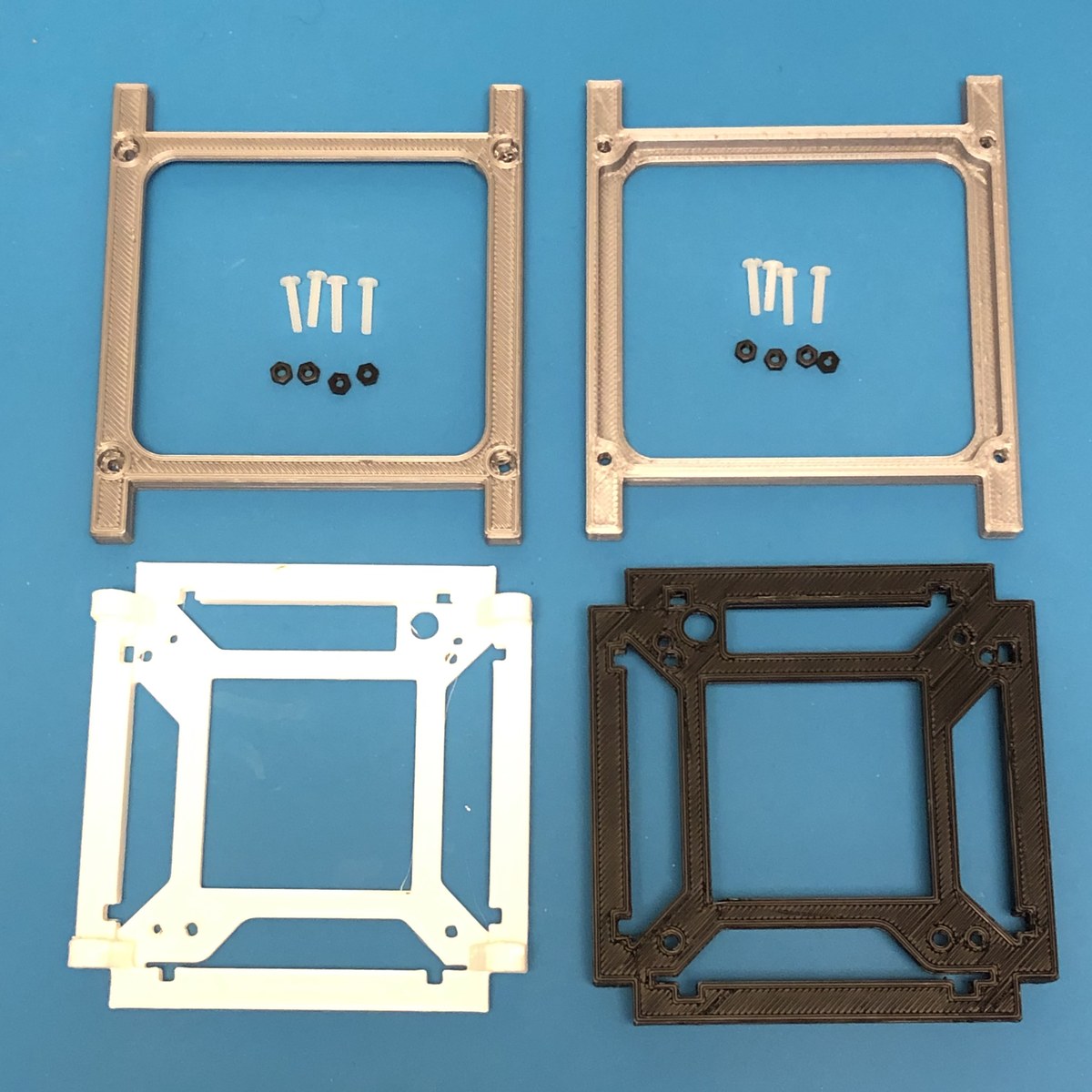
The 1U form factor and frame
The CubeSatSim adopts the 1U CubeSat form factor and uses a 3D-printed frame structure to hold the board stack, batteries, solar panels, and antenna.23 Using the real CubeSat geometry is deliberate: it lets the model sit in the same deployment rails, demonstrate the same solar-panel layout, and teach the same mechanical-integration lessons as a flight unit.
System architecture — the board stack
Electrically, the CubeSatSim is a stack of boards that plug onto a Raspberry Pi, plus a set of solar panels. The exact composition has evolved across hardware versions (see “Version drift” below), but the architecture is consistent: a single-board computer does the “flight software,” a power board manages battery + solar, a radio/main board generates and filters the RF downlink, and a payload board adds sensors and a microcontroller.
A representative recent kit consists of:346
- Raspberry Pi Zero 2 single-board computer (the “flight computer”), with a programmed micro-SD card, a Pi Camera, and a USB OTG cable.
- Main board — the radio board, carrying the FM transmitter module and the 433 MHz low-pass (harmonic) filter; in the current kit this board is labeled the “STEM Payload Board” and carries a Raspberry Pi Pico W microcontroller.
- Battery board — battery holder + charging/power management, with a JST jumper.
- Solar board — solar-input management, with a JST jumper, fed by ten solar panels (JST-connected).
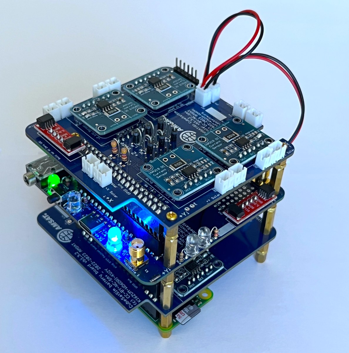
How the boards stack
The boards mount as HATs (Hardware Attached on Top) — they plug onto the Pi’s 40-pin header and onto each other. In the Paper 5-era design, the stack from the bottom up is: Raspberry Pi Zero WH → Main PCB → Battery Board → STEM Payload Board, where the Main PCB integrates the transmitter, battery charging, and solar-power functions onto one board that sits directly on the Pi.2 This HAT-stack approach keeps the whole avionics package inside the 1U envelope and makes the model easy to assemble and service.
The four subsystems
Regardless of board count, the design decomposes into four subsystems, each developed in depth in a later volume:
Table 1 — Regardless of board count, the design decomposes into four subsystems, each developed in depth in a later volume
| Subsystem | What it does | Key parts | Deep dive |
|---|---|---|---|
| Compute / “flight software” | Runs the telemetry, mode logic, and camera | Raspberry Pi Zero (2) + micro-SD; Pi Pico W on the payload board | Vol 3 |
| Power & solar | Battery charging, solar input, bus regulation, RBF cutoff | Battery board, Solar board, 10× solar panels | Vol 2 (theory) + Vol 3 (build) |
| RF payload (downlink) | Generates + filters the 70 cm telemetry signal | Main board: FM module + 433 MHz low-pass filter | Vol 2 (theory) + Vol 4 (schematic) |
| Sensors / STEM payload | Voltage/current/temperature sensing + camera | INA-class sensors, temperature sensors, Pi Camera | Vol 3 |

Telemetry and the downlink, at a glance
The CubeSatSim’s whole reason for existing is its RF downlink. It transmits multi-channel voltage, current, and temperature telemetry — plus SSTV camera images — in the 70 cm (UHF) amateur band, with a default monitoring frequency of 434.900 MHz Narrowband FM.451 On power-up it boots for about 30 seconds, then sends a CW (Morse) identification — the letters “de” followed by the operator’s callsign — before streaming telemetry.1
It supports several modulation modes drawn from real amateur-satellite practice — AFSK, FSK (including the “DUV”, data-under-voice, style used by AMSAT Fox satellites), BPSK, and SSTV for images.52 The theory behind each of these, and why a satellite would choose one over another, is the subject of Vol 2.
On the ground, the signal is received with an inexpensive RTL-SDR and decoded with AMSAT FoxTelem, the same open-source Java tool used for real Fox-series satellites; AFSK telemetry can alternatively be decoded with tools like Multimon-ng.1 Ground-station setup is the subject of Vol 5.
Version drift — read this before trusting any single spec
The CubeSatSim is an actively developed open-source project, and its hardware has moved through v1.x → v2.0 → v2.1, plus a generation that adds a Raspberry Pi Pico W on a “STEM Payload Board.” Consequently, sources legitimately disagree on details depending on which version they describe:
- Board count: “three custom PCBs” (Main/Battery/Solar) in some descriptions vs. a “four-board stack” in others.34
- Single-board computer: Raspberry Pi Zero W (earlier papers) vs. Raspberry Pi Zero 2 (WH) (current).24
- Microcontroller: the current kit adds a Pi Pico W on the payload board; earlier designs did not.62
Throughout this deep dive, each hardware claim is anchored to a version and a source. The authoritative version map is the GitHub hardware/ tree (folders v1.1, v2.0, beta-v1.3.2), which holds the gerbers, schematics, and board images for each revision.7
Where this fits in Jeff’s projects
This is an Electronics build sub-project (build + theory + schematics + usage), cross-referenced to the amateur-radio side:
- Ground-station receivers live in the Scanners_and_Radios project; its Vol 4 covers the frequency planning / license envelope that governs transmitting here.
- Antenna and regulatory/RF-safety depth lives in Hack Tools/Antennas (Antennas Vol 31). Field-use sections cross-link there rather than re-deriving the rules.
Planned volume breakdown
- The System — Vol 1 — overview & system architecture (this volume)
- The Theory — Vol 2 — power/solar energy budget, telemetry framing, the modulation modes (AFSK / FSK-DUV / BPSK / SSTV), link budget, and the Part 97 / 70 cm transmit envelope
- The Build — Vol 3 — bill of materials, board-by-board assembly, the power/solar subsystem, software flashing, and machining the 1U frame from aluminum on a Carbide 3D Nomad 3 (alternative to the printed frame)
- The Schematics — Vol 4 — annotated board-level circuit design (Main / Battery / Solar / Payload)
- The Usage — Vol 5 — power-up sequence, transmit modes, and receiving/decoding telemetry on an RTL-SDR + FoxTelem ground station
References
Footnotes
-
Johnston et al., “AMSAT CubeSatSim” (Paper 7) — https://cubesatsim.com/content/CubeSatSimPaper7.pdf (1U Pi-Zero functional model; “monitoring 434.900 MHz Narrowband FM (NFM) … after about 30 seconds, begin transmitting … a CW signal which is the text letters ‘de’ … then the callsign”; FoxTelem on Raspberry Pi via ARISS Radio Pi image; Multimon-ng). ↩ ↩2 ↩3 ↩4 ↩5 ↩6 ↩7
-
Johnston et al., “AMSAT CubeSatSim” (Paper 5) — https://cubesatsim.com/content/CubeSatSimPaper5.pdf (board stack “from the bottom, Raspberry Pi Zero WH, Main PCB, Battery Board, STEM Payload Board”; FSK DUV + BPSK modes; 433 MHz band-pass filter; FoxTelem v1.09). ↩ ↩2 ↩3 ↩4 ↩5 ↩6 ↩7
-
CubeSatSim project site — https://cubesatsim.com/ (“a fully open source low cost satellite emulator that runs on solar panels and batteries, transmits UHF radio telemetry, has a 3D printed frame”; “three custom PCBs, a Raspberry Pi Zero 2, and a Raspberry Pi Pico”). ↩ ↩2 ↩3 ↩4 ↩5
-
CubeSatSim GitHub Wiki — https://github.com/alanbjohnston/CubeSatSim/wiki (“Raspberry Pi Zero 2 WH with Pi Camera, Battery Board, Main Board with FM module, and Solar Board”; “Multi-channel voltage, current, and temperature telemetry transmitted in the Amateur Radio UHF band”). ↩ ↩2 ↩3 ↩4 ↩5
-
AMSAT HARC Presentation — https://www.cubesatsim.org/pres/AMSAT_HARC_Presentation.pdf (“Transmits housekeeping telemetry on the 70 cm ham band using AFSK … FSK … or BPSK … and also transmits SSTV … images”). ↩ ↩2 ↩3
-
CubeSatSim Wiki — Kit — https://github.com/alanbjohnston/CubeSatSim/wiki/Kit (“Fully assembled Main board (labeled STEM Payload Board) … fully programmed Raspberry Pi Pico W”; “Raspberry Pi Zero 2 with programmed micro SD card … Pi Camera and USB OTG cable”; “Solar Panels (10x) with JST connectors”). ↩ ↩2
-
CubeSatSim hardware tree — https://github.com/alanbjohnston/CubeSatSim/tree/master/hardware (“gerbers, schematics, and images of the Main, Battery, and Solar boards”; hardware version 2.0). ↩